Paleta wall mount – Alera Lighting PAL WM User Manual
Page 2
© 2010 Alera Lighting, a division of Hubbell Lighting, Inc. Because of continuing product improvement programs, Alera Lighting reserves the right to change specifications
without notice. 701 Millennium Blvd. Greenville, SC 29607 / Tel 864.678.1000 / Tech Support 864.678.1580 / Website www.aleralighting.com
Page 2/2 Rev. 01/15/10
CuRveS / PAL WM TID
Paleta Wall Mount
Technical Installation Data
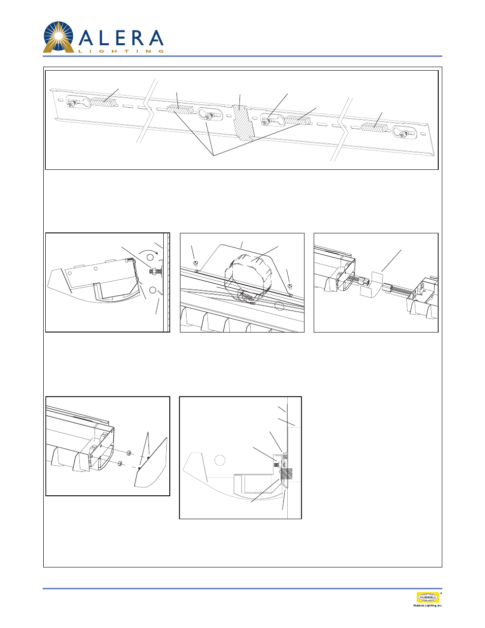
Step 1
Using mounting information and data chart from previous page, install bracket to wall using continuous slots. Ensure
bracket is level. At each mounting location (three for 8 ft. fixtures), insert stud/nut assembly into hole on embossed slots of
bracket and slide to inside edge of flange. Apply foam strip to each stud location. Place spacer into v-groove of bracket to
align and install next bracket. Continue mounting brackets until row is complete.
Omit (1) Foam Strip and (1) Stud/Nut Assembly for center mount on 8 ft. fixtures.
Foam Strip
Foam Strip
Bracket Spacer
Foam Strip
Foam Strip
Remaining Stud/Nut Assembly
can be used in either slot
Use nut to level the fixture
after it is installed.
Wall
Cleat
Groove
Screw
Wire
Connectors
J-Box Cover
Screw
J-Box
Aligner
Step 2
Remove ballast cover on luminaire. Slip
cleat in v-groove on bracket (1) and
push stud through keyhole slot (2).
Step 3
Pull wires from J-box into fixture
housing and splice to harness as
required. Install J-box cover to bracket
with screws supplied.
Step 4
Repeat step 2 for next fixture. Connect
harness plugs together. Slide fixture
with aligner to mate with previous
fixture in row. Secure fixtures using
supplied nut and bolt. Continue to
repeat step 3 as required.
Step 5
When all fixtures in row have been
installed and leveled, attach end cap
using nuts provided.
Cross Section
Screws
Wall Bracket
Bushing for Feed Wires
UMS Stud with Nut
Foam Strip
J-Box
J-Box Cover