Alera Lighting ASCL User Manual
Page 2
t
echnical
i
nStallation
D
ata
19-2.1
C
AL 02/03
, w
all
m
ount
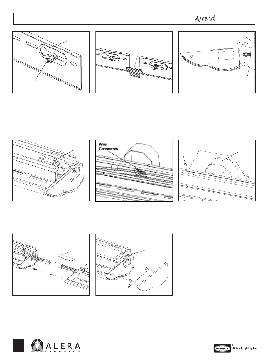
Step 1
Using mounting information and data chart
from previous page, install bracket to wall
using continuous slots. Ensure bracket is
level. Insert stud/nut assembly into hole on
embossed slots of mounting bracket and slide
to edge of flange.
Step 2
Place spacer into v-groove to align and
install next wall bracket. Continue mounting
brackets until row is complete.
Step 3
Remove ballast cover on fixture. Slip cleat
into lower v-groove on mounting bracket (1)
and push stud through keyhole slot (2).
Step 4
Level fixtures by adjusting nut on stud at each
end of fixture.
Step 5
Pull wires from J-box into fixture housing and
splice to harness as required.
Step 6
Install J-box cover to mounting bracket with
screws as required.
Step 7
Repeat step 3 for next fixture. Connect
harness plugs together. Slide fixture to mate
with previous fixture in row. Secure fixtures
using supplied nut and bolt. Snap wire
channel clip on bottom edge of wireway as
shown.
Step 8
When all fixtures in row have been installed
and leveled, slide bracket into internal end
cap as shown. Attach and align external end
cap with screws provided. Replace all ballast
covers.
Edge of Flange
Stud/Nut
Assembly
Spacer
Wall
Cleat
Groove
2
1
Nut
Screw
J-box
Clip
Bracket
Screws
701 Millennium Blvd
Greenville SC 29607 • (864) 678-1000
www.aleralighting.com
We are architectural fluorescent lighting
Subject to change without notice.