A+class, Master/row control switch – Alera Lighting APCS MRCS User Manual
Page 2
Integrated Controls / A+CLASS
™
MASter/row ControL SwitCh tiD
A+CLASS
™
MASter/row ControL SwitCh
technical installation Data
© 2013 Alera Lighting, a division of Hubbell Lighting, Inc. Because of continuing product improvement programs, Alera Lighting reserves the right to change specifications
without notice. 701 Millennium Blvd. Greenville, SC 29607 / Tel 864.678.1000 / Website www.aleralighting.com
Page 2/2 Rev. 08/05/13 H72-00435US Patent #8,436,542
instALLAtion instrUctions
1. Prepare the installation site, as necessary, to install the switch.
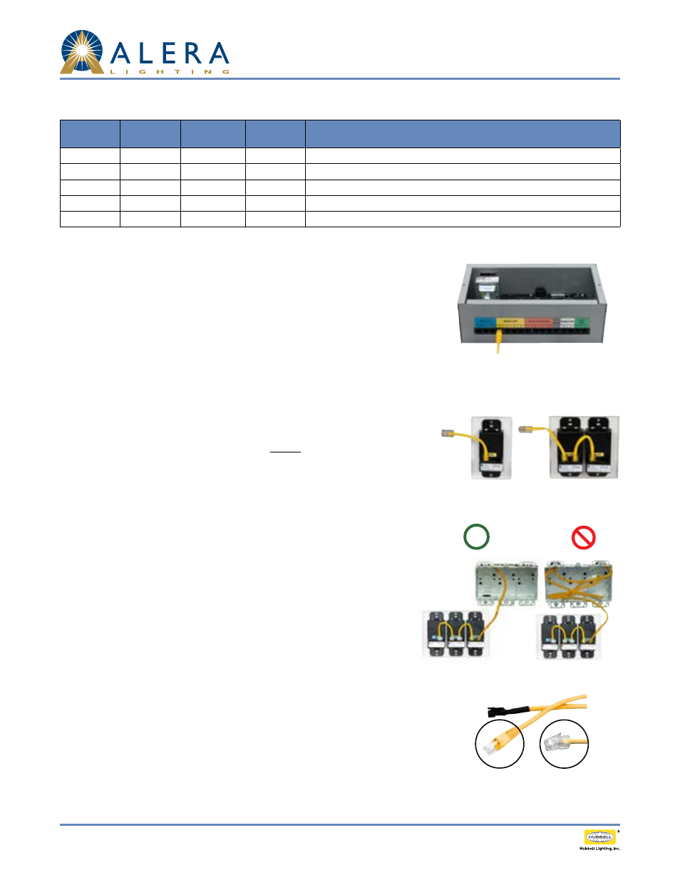
2. Plug the 50' Yellow CAT5 cable into the Yellow Master/Row Control connector on the
Classroom Control Module (See Figure 1). Each CAT5 connection will operate properly from
any available Yellow Master/Row Control port. Multiple connections are required under the
following circumstances.
a. When multiple Master On/Off controls are used and each has a home run back to the CCM.
b. When a Master On/Off control is used in conjunction with a gang of Row on/off controls.
c. When multiple Row control gangs are used in the same classroom and each has a home run
back to the CCM.
3. Route the Yellow cable from the Classroom Control Module to the Master Control Switch or
Row Control Switch. If routing multiple switch stations, up to four connections may be made
as home run connections. Note: Low voltage wiring must be isolated from line voltage wiring.
Consult National and Local Electrical Codes for conduit requirements.
4. Plug the Yellow cable into the Master Control Switch or Row Control Switch (See Figure 2).
Verify solid snap-in connection.
5. If multiple switches are ganged together, daisy-chain them together using 3" Yellow jumper
cable (See Figure 3). Verify solid snap-in connection(s).
6. Remove excess cable from wall box prior to insertion of switch(es). CAT5 connection to the
switch must remain straight, true, and free of pressure or interference from excess cable
in box. (See Figure 4). Test functionality of switch prior to installing the switches into the
electrical box.
7. Perform system setup and/or programming activities as applicable in accordance with the
instructions of the CCM (Classroom Control Module).
8. Verify switch functionality by pressing the switch button(s) and confirm proper system
response.
note: EasyConnect cord upgrade may be provided. EasyConnect can be identified in Figure 5 .
troUbLeshooting tips
1. Check for solid connections between all components.
2. Ensure power to CCM is engaged.
3. Ensure wall box does not include excess cable; CAT5 connections must be straight and true
without interference. See step 6 above.
4. Consult CCM programming manual for additional assistance.
switch stAtion iDentiFicAtion
Fig. 2
Fig. 1
Fig. 3
Side Label
P/N
Back Label
No. of
Buttons
Button
Label(s)
Function
APCS-MC
MC
2
ON, OFF
On/Off control for all rows of general and/or A/V lighting
APCS-RCR1
RCR1
1
ROW 1
On/Off control for one row of general and/or A/V lighting designated Row 1
APCS-RCR2
RCR2
1
ROW 2
On/Off control for one row of general and/or A/V lighting designated Row 2
APCS-RCR3
RCR3
1
ROW 3
On/Off control for one row of general and/or A/V lighting designated Row 3
APCS-RCR4
RCR4
1
ROW 4
On/Off control for one row of general and/or A/V lighting designated Row 4
Fig. 5
1. (Cat cable end may look like
A or B)
Fig. 4
A
B
a