Aeromotive 17143 - 96-98 1_2 4.6L DOHC COBRA A1000 FUEL SYSTEM User Manual
Page 4
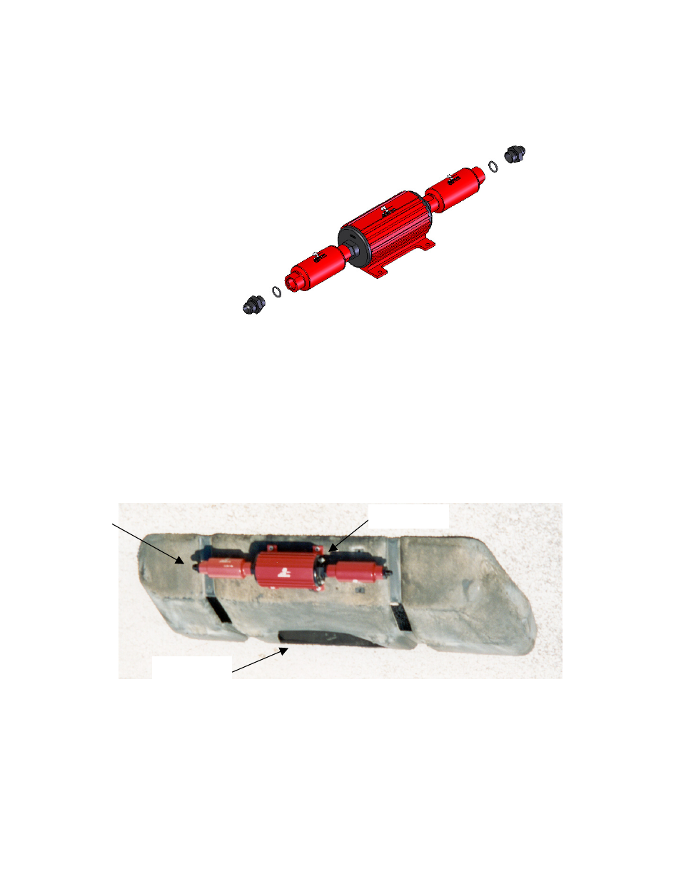
1-9. Install one of the supplied AN-10 o-rings on the cutoff side of the AN-10 cutoff union fitting, if not already installed,
and install on the inlet side of the pump / filter assembly.
1-10. Install one of the supplied AN-10 o-rings on the AN-10 cutoff side of the AN-10 cutoff to AN-08 reducer union fitting,
if not already installed, and install on the outlet side of the pump / filter assembly.
Figure 1-2
1-11. Position the fuel pump / filter assembly from above on the opposite end of the plastic fuel tank shield as the sump
cutout. Center the pump / filter assembly in all directions on the flat. Using the fuel pump as a guide, mark the four
pump mounting holes. Insure there are no obstructions behind the plastic fuel tank shield and drill four ¼” mounting
holes.
1-12. The fuel pump should be installed such that when the plastic fuel tank shield is installed the fuel pump outlet is on
the driver side of the vehicle. Secure the fuel pump to the plastic fuel tank shield by installing each of the four ¼”
carriage bolts from the inside of the fuel tank shield, through the fuel tank shield and through the fuel pump mounting
holes. Install each of the four provided flat washers and nuts on the bolts and tighten. The plastic fuel tank shield now
should look similar to the one shown below.
1-13. Inspect the inside of the plastic fuel tank shield for any sharp edges that could puncture the fuel tank. If any sharp
edges are found, correct before proceeding.
1-14. Position the plastic fuel tank shield on the Aeromotive fuel tank.
1-15. Using the two supplied 90-degree AN-10 hose ends as a guide, measure the length of AN-10 steel braided line
needed to connect the fuel tank sump outlet to the fuel pump / filter assembly inlet.
1-16. Cut and assemble the steel braided hose and hose ends as shown in Section 4.
Inlet
Pump outlet
Sump Cutout