Aeromotive 17156 - COBRA JET ENGINE KIT User Manual
Page 7
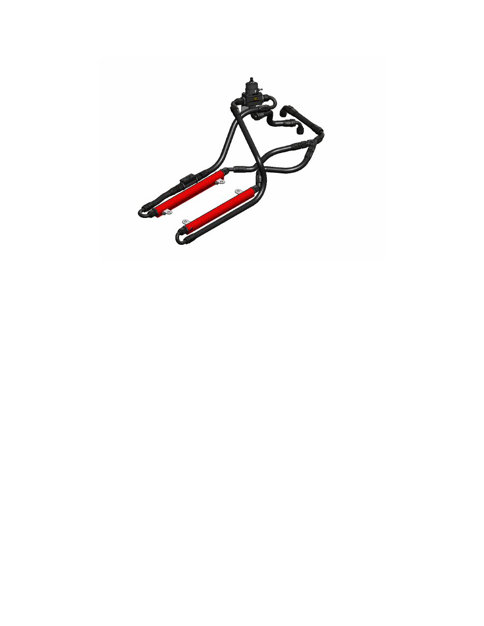
34. With the supplied vacuum tee, tee into the manifold vacuum/pressure port (located under the blower
drive snout) and route vacuum line to the regulator.
35. Use the supplied hose clamps to position the hoses neatly where you would like them.
36. Remove the 1/8” port plug from the face of the regulator so the fuel sample valve can be placed there.
Use thread sealant on the threads as they are NPT. Place a fuel pressure gauge on the fuel sample
valve so pressure can be set.
37. Reverse steps 1-10 for reassembly.
38. With the fuel pressure gauge registering fuel system pressure, check for fuel leaks from and
around the Aeromotive regulator, fuel rails, all fuel lines and connections! If any fuel leaks are
found, turn the ignition key to the OFF position, remove any spilled fuel and repair the leak
before proceeding!
39. Once the fuel pressure gauge registers fuel system pressure and there are no fuel leaks, start the
engine and adjust the regulator to the desired fuel pressure. Turning the adjustment screw clockwise
will increase fuel pressure. Refer to the shop manual for the proper fuel pressure setting.
40. Once the desired fuel pressure is achieved, tighten the regulator adjustment jam nut and attach the
vacuum line.
41. Turn off the engine and allow it to cool. If you do not want to keep the fuel pressure gauge on the
vehicle, relieve the fuel system pressure as instructed in the appropriate vehicle service manual.
Remove the fuel pressure gauge and reinstall the 1/8 NPT pipe plug, using thread sealant.
42. Test drive the car to insure proper operation and re-check the fuel system for leaks. If any leaks are
found, immediately shutoff the engine and repair the leak(s)!