Aeromotive 17202 - A2000 FUEL PUMP KIT User Manual
Page 3
1-8. Making sure to mount the pump in the upright position and using the pump mounting bracket as a template, mark and
drill two mounting holes to accept ¼” bolts (not provided). Mount the pump bracket using two ¼” bolts, nuts and lock
washers (Not provided).
Note: Be sure to route all fuel lines clear of any moving suspension or drivetrain components, and any exhaust
components! Protect fuel lines from abrasion and road obstructions or debris.
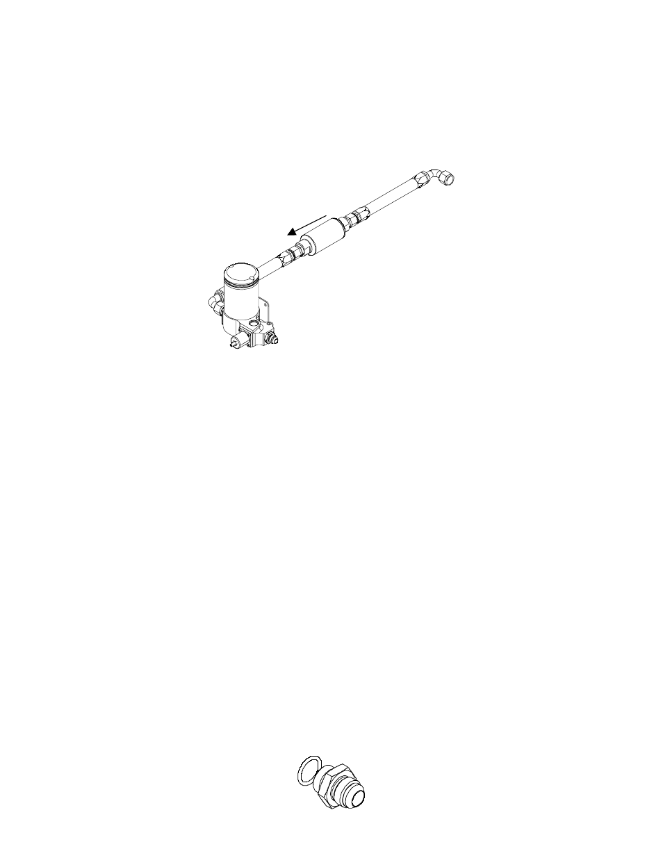
1-9. Using the system diagram below, determine the approximate location of the fuel filter in the system.
1-10. Using one of the supplied 90-degree AN-10 hose ends and one of the supplied AN-10 straight hose ends as a
guide, measure the length of AN-10 steel braided line needed to connect the fuel tank or fuel cell outlet to the fuel
filter inlet. This section of fuel line should be as short as possible to reduce the tendencies for vapor lock, cavitation,
and premature wear of your Aeromotive fuel pump.
1-11. Cut and assemble the steel braided hose and hose ends as shown in Section 2.
1-12. Using the above steel braided line assembly, connect the hose ends to their appropriate locations and tighten.
1-13. Repeat steps 1-10 thru 1-12 for the AN-10 steel braided line between the fuel filter outlet and fuel pump inlet.
1-14. In the vehicles engine compartment determine where your fuel pressure regulator (Not supplied) is or will be
mounted. We recommend Aeromotive p/n 13201 for 2-port applications and Aeromotive p/n 13203 for 4-port
applications.
Note: Be sure to route all fuel lines clear of any moving suspension or drivetrain components, and any exhaust
components! Protect fuel lines from abrasion and road obstructions or debris.
1-15. Using the remaining two AN-10 straight hose ends as a guide, measure the length of AN-10 steel braided line
needed to connect the fuel pump outlet to your fuel pressure regulator (Not Supplied).
1-16. Cut and assemble the steel braided hose and hose ends as shown in Section 2.
1-17. Using the above steel braided hose assembly, connect the hose ends to their appropriate locations and tighten.
Note: Be sure to route all fuel lines clear of any moving suspension or drivetrain components, and any exhaust
components! Protect fuel lines from abrasion and road obstructions or debris.
1-18. Place the supplied AN-08 o-ring on the cutoff side of the AN-08 cutoff union.