Danger, Warning, Caution – Elmo Rietschle L-BV3 User Manual
Page 17
Commissioning
© Gardner Denver Deutschland GmbH
17 / 32
610.444430.40.000
DANGER
Electrical danger!
The electrical connection may be carried out
by trained and authorized electricians only!
DANGER
Electrical danger!
Before beginning work on the unit or system,
the following measures must be carried out:
Deenergize.
Secure against being switched on again.
Determine
whether
deenergized.
Ground and short-circuit.
Cover or block off adjacent energized parts.
DANGER
Electrical danger!
Depending on the charging state of the
capacitors, a residual voltage may be present
on the terminals in the terminal box.
After opening the terminal box cover, it must
be ensured that the capacitors are completely
deenergized:
Measure the voltage at the corresponding
jumpers (see the circuit diagram in the
terminal box).
Dissipate the residual voltage with suitable
means if necessary.
The capacitors must be completely
deenergized.
WARNING
Danger due to gauge pressure and vacuum!
Danger due to escaping fluid!
Before beginning work on the unit or system:
Interrupt supply of operating liquid.
Bleed lines and vacuum pump/compressor
(depressurize).
The further procedure is again dependent
on the unit operating mode:
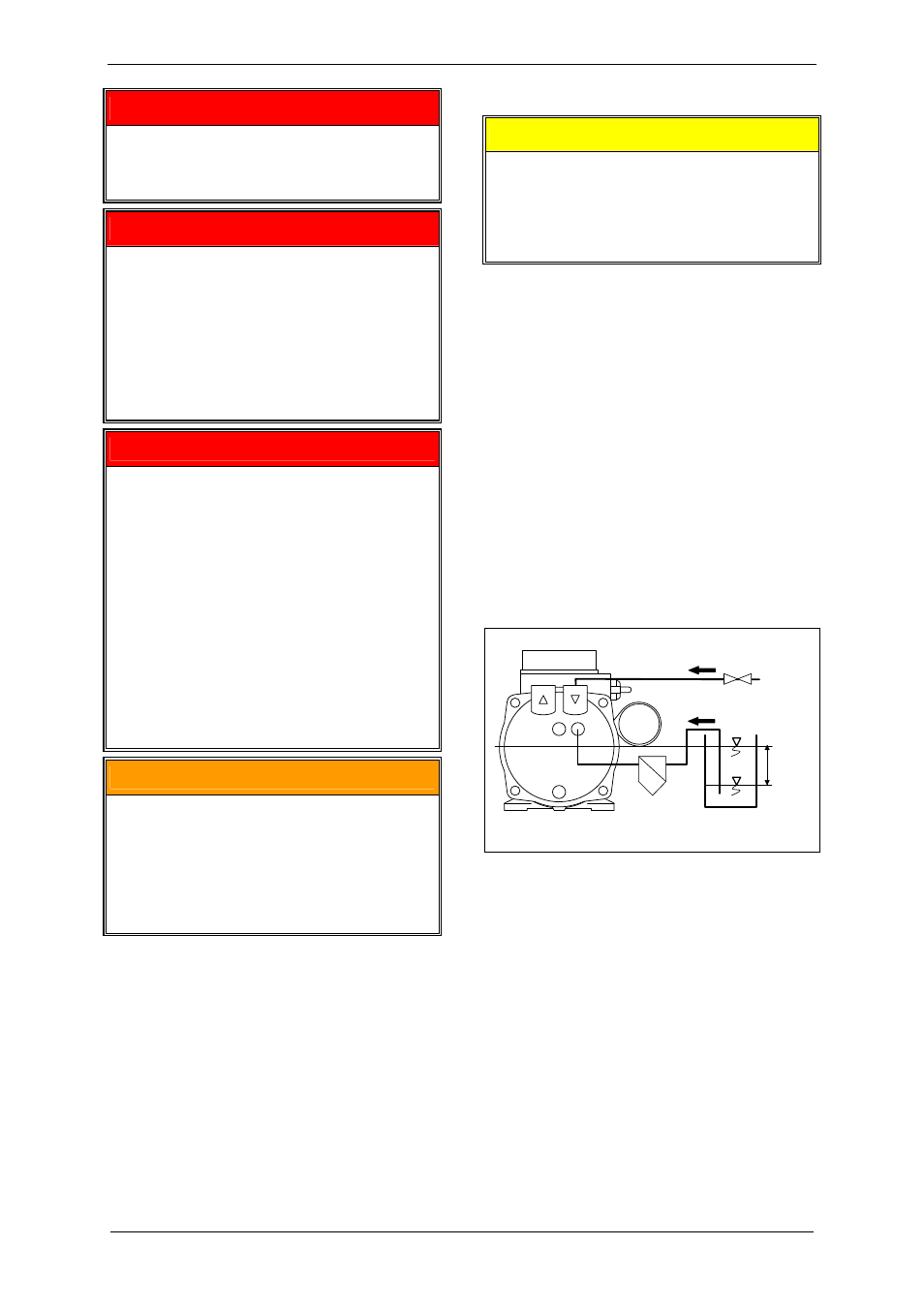
7.2 Self-priming
operation
CAUTION
The liquid level in the feed pipe or in the
reservoir may not exceed the height of the
shaft center of the pump-motor unit!
If this height is exceeded, too much liquid gets
into the pump-motor unit. Damage can occur!
See Fig. 4, Pg. 17.
Here the following must be watched:
The pump-motor unit must be pre-throttled
on the inlet side. This means a vacuum of
at least 80 kPa abs.
[11.6 psia] must be
present in the inlet pipe (Item B) at switch-
on.
During switch-on, the liquid level in the feed
pipe (Item A) and in the reservoir (Item C)
respectively must be at the same level as
the center of the unit shaft (Item 1).
During operation the liquid level in the
reservoir (Item C) may not drop below
approx. 1 m [3.28 ft] below
the center of
the unit shaft (Item 1).
1
2
1 m
3,28 ft
80 kPa abs
11,6 psia
6104443001005
B
A
C
Fig. 4: Self-priming operation
A Feed pipe for operating liquid
B Inlet
pipe
C Reservoir for operating liquid
1 Required liquid level when switching on
2 Min. liquid level during operation
Starting the pump-motor unit:
Switch on the unit.
The operating liquid is sucked in.