Gorman-Rupp Pumps 16C2-F5L 1338631 and up User Manual
Page 30
OM−01876
10 SERIES
MAINTENANCE & REPAIR
PAGE E − 9
shaft (42) with the V" notch positioned over the
shaft key.
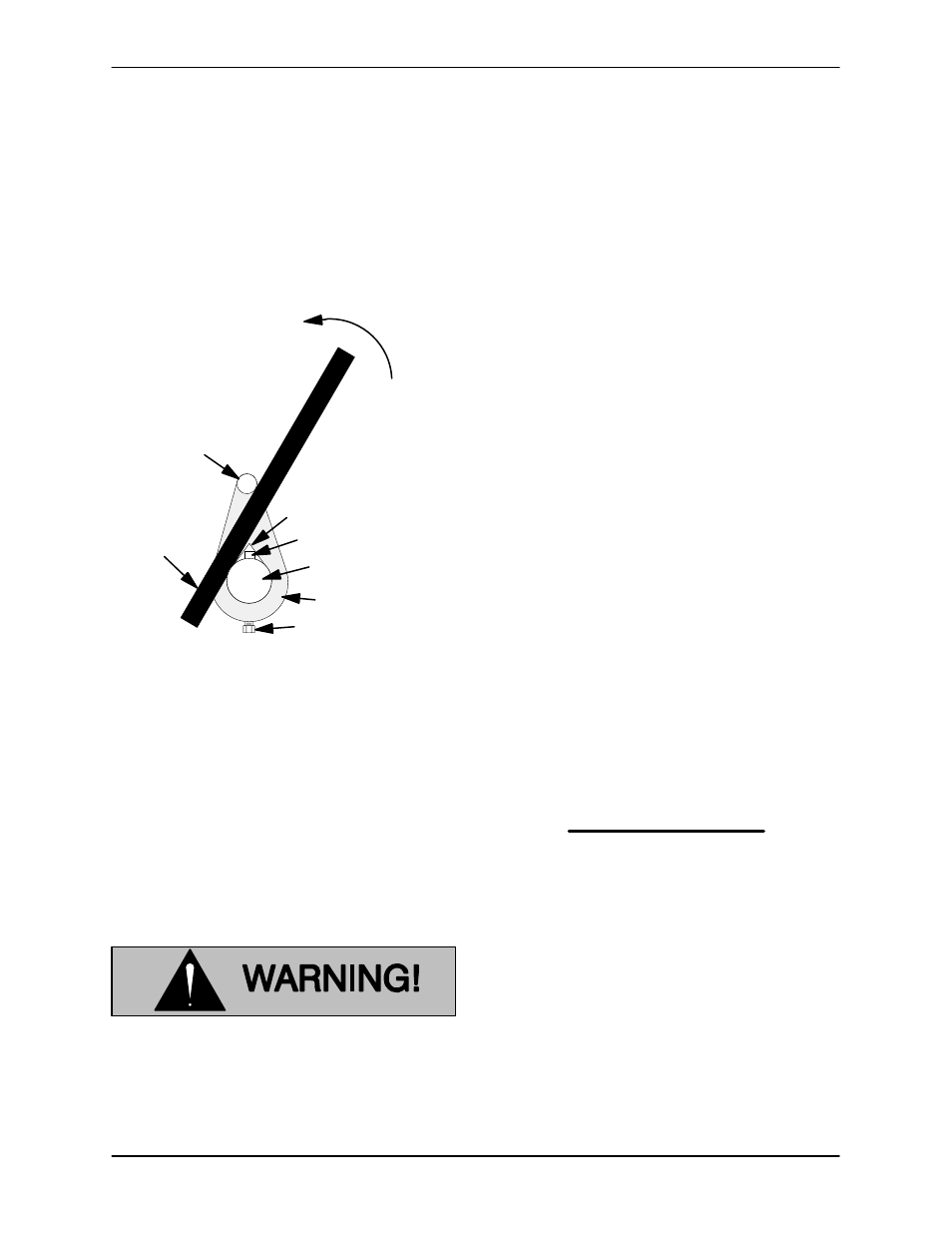
With the impeller rotation still blocked, see Figure 4
and use a long piece of heavy bar stock to pry
against the arm of the lathe dog in a counterclock-
wise direction (when facing the drive end of the
shaft). Use caution not to damage the shaft or key-
way. When the impeller breaks loose, remove the
lathe dog, key and wood block.
Turn
Counterclockwise
Lathe Dog Arm
V" Notch
Shaft Key
Impeller
Shaft
Lathe Dog
Setscrew
Heavy
Bar Stock
Figure 4. Loosening Impeller
Pump Casing Removal
(Figure 2)
Remove the nuts (16) securing the pump casing to
the intermediate (21). Install a standard 5/8-11
UNC−2B lifting eye in the tapped hole in the top of
the pump casing. Be sure to screw the eye into the
casing until fully engaged. Use a hoist and sling of
suitable capacity to separate the casing from the
seal plate and intermediate.
Do not attempt to lift the complete pump
unit using the lifting eye. It is designed
to facilitate removal or installation of in-
dividual components only. Additional
weight may result in damage to the
pump or failure of the eye bolt.
Remove the pump casing gaskets (49).
Impeller Removal
(Figure 2)
Unscrew the impeller in counterclockwise direc-
tion (when facing the impeller). Use caution when
removing the impeller; tension on the shaft seal
spring will be released as the impeller is un-
screwed. Inspect the impeller and replace if
cracked or badly worn.
Slide the impeller adjusting shims (31) off the im-
peller shaft (42). Tie and tag the shims, or measure
and record their thickness for ease of reassembly.
Seal Removal and Disassembly
(Figure 2)
To remove the seal assembly (3), remove the
grease cup and piping (17, 18 and 19). Slide the
seal plate and seal parts off the shaft as a single
unit. Be careful not to drop or damage any seal
parts.
Carefully remove the stationary and rotating seal
elements, packing rings, seal spring, and spacer
sleeve from the seal plate.
NOTE
The seal assembly may be removed without com-
pletely disassembling the pump by removing the
impeller through the back cover opening and using
a pair of stiff wires with hooked ends to pull the seal
parts out of the seal plate.
Inspect the seal liner (76) for wear or grooves
which could cause leakage or damage to the seal
packing rings. The seal liner is a press fit in the seal
plate, and does not normally require replacement.
If replacement is necessary, see Seal Installation.
If no further disassembly is required, refer to Seal
Reassembly And Installation.
Shaft and Bearing Removal and Disassembly
(Figure 2)
When the pump is properly operated and main-
tained, the intermediate should not require disas-