SM Pro Audio IN5E: USB Audio Interface and Stand alone Mixer User Manual
Page 7
7
Rear Panels Controls – Front Panel Controls
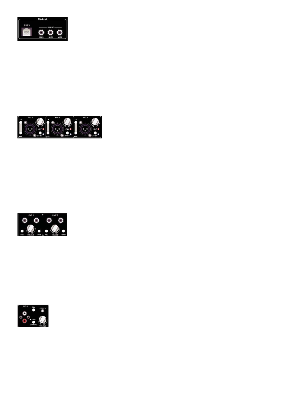
5.6 Ethernet input and microphone insert point
The IN5E supports you with a new breed of analog audio distribution features.
With just one standard CAT5 cable it is now possible to transmit up to three
channels of audio. Perfect, if you are going to use the IN5E as recording inter-
face in a studio. No more cable hassles and fear of broken audio cables during a recording session. This
new connection is truely passive without any influences on th sound! Just check your local dealer and
www.violetaudio.com for compatible products.
The three TRS inserts are for connecting any dynamics of effects between the connected microphones
at the front panel. So if you like to spice up your vocals directly while recording, these are the right
connections.
6.
Front Panel Connections and Control Knobs/Switches
6.1 XLR Mic Input controls
Independent (3 x) rotary gain controls, switchable Phantom power,
peak lights, and a record/monitor enable switch.
This is where you can connect up to three microphones, control their
input gain, and choose either to monitor the signal directly to your main outputs for monitoring, or to
send the source to the REC outputs and subsequently to your recording device. Connect a microphone
using a standard XLR type microphone cable and turn up the volume knob to an acceptable level. If your
microphone is a condenser microphone that requires phantom power, depress the 48V switch to enable
power to your mic. The REC switch directs the microphone source signal to the REC output on the rear
panel when in the drepessed position. When in the non-depressed position the signal is routed directly
to the main outputs on the rear panel. The peak light illuminates to indicate when the mic pre-amp is
overdriven with excessive input signal. If illuminated, reduce the volume to avoid distortion of your micro-
phone signal.
6.2 Stereo line Input controls
Independent (2 x) rotary volume controls, -20dB pad, and a record/monitor
enable switch.
This is where you can connect up to two stereo (L&R) line level devices (keyboards,
modules etc), control their input gain, and choose either to monitor the signal directly to your main out-
puts for monitoring, or to send the source to the REC outputs and subsequently to your recording device.
Connect your stereo (L&R) line level device with a standard 1/4” audio cables and turn up the volume
knob to an acceptable level. A -20dB PAD switch is provided to reduce the input gain on very high input
signals. If your signal is distorting, depress the -20dB switch to adjust to a more suitable level. The REC
switch directs the line level source signal to the REC output on the rear panel when in the drepessed posi-
tion. When in the non-depressed position the signal is routed directly to the main outputs on the rear
panel.
6.3 Phono Input controls
Independent rotary volume control, line/phono switch, and a record/monitor enable switch.
This is where you can connect one stereo phono/line level device, control their input gain,
and choose either to monitor the signal directly to your main outputs for monitoring, or to
send the source to the REC outputs and subsequently to your recording device.
Connect your stereo (L&R) phone/line level device with a standard RCA audio cable and turn up the vol-
ume knob to an acceptable level. A line/phono switch is provided for the stereo pair of the input which
toggles the use of the input as either a fully operational RIAA phono pre-amp or as standard RCA line level
input. The REC switch directs the phono/line level source signal to the REC output on the rear panel when
in the drepessed position. When in the non-depressed position the signal is routed directly to the main
outputs on the rear panel.