Extron Electronics VS 200 SL User Guide User Manual
Page 8
Extron • VS 200 SL • User’s Manual
Extron • VS 200 SL • User’s Manual
Rack Mounting
2-4
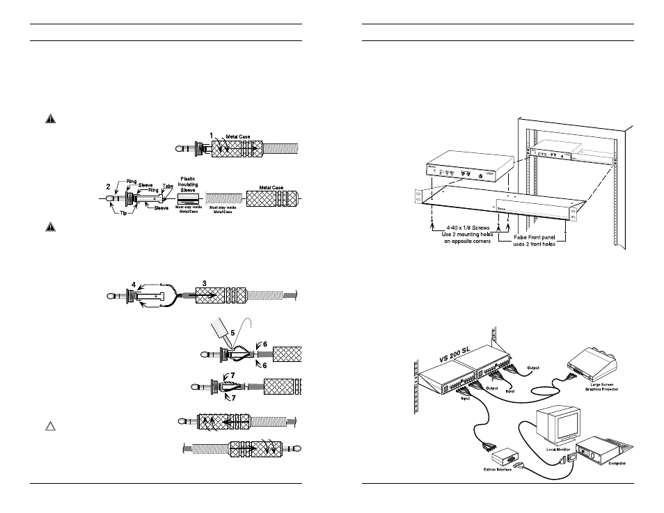
Mounting the VS 200 SL on a 1U Rack Shelf
A 1U rack shelf accommodates two units the size of a VS 200 SL.
Each of these devices has two threaded holes in its base plate for
shelf-mounting.
1. If the VS 200 SL has feet, remove them.
2. Align the VS 200 SL over the shelf so that its two threaded holes
line up with two of the holes in the 1U shelf.
3. Use two 4-40 x 1/8" screws
to mount the VS 200 SL to
the 1U shelf.
VS 200 SL Rack Mount
4. If the shelf is not already mounted in the rack, use the supplied
hardware and follow the instructions that came with the
1U Shelf (p/n 60-190-01).
5. When the VS 200 SL is mounted, continue the installation by
connecting the input, output, and power cables.
VS 200 SL
Connection Diagram
ShiftLock Cables
2-3
Wire
Flex-Spring
8
Making ShiftLock Cables
Extron supplies connectors for making ShiftLock cables; the user
supplies the cable. Twisted pair cable can be used – up to 50 feet
in length.
The illustration below shows the steps for a making a cable using
twisted pair. Do each step for both ends of the cable. Make as
many cables as required.
___ Although the color of the wire is not important, you must keep the
same wire color assignments for both ends of the cable.
1. Unscrew the metal case.
2. Identify the contacts, parts, and connections.
___ The plastic insulator must be inside to prevent electrical contact
with the metal case.
As shown here, the connectors have three contacts. However,
only the “Tip” and “Ring” contacts are used.
3. Insert the metal case (insulator and flex spring) over the cable.
4. Strip the wires and attach them
through the holes in the contacts.
5. Solder both connections.
6. Bend the tabs around the cable
jacket.
7. Press the wires and contacts
inward to allow the Insulator
and metal case to slide over
easily.
___ Do not allow the contacts to
touch each other.
8. Screw the metal case
onto the connector.
Connect the cables according to the example on page 2-2.