Connections and settings, Connections, And settings – Extron Electronics MTP 4T 15HD RS User Guide User Manual
Page 11
MTP 4T 15HD RS • Installation and Operation
6
Connections and Settings
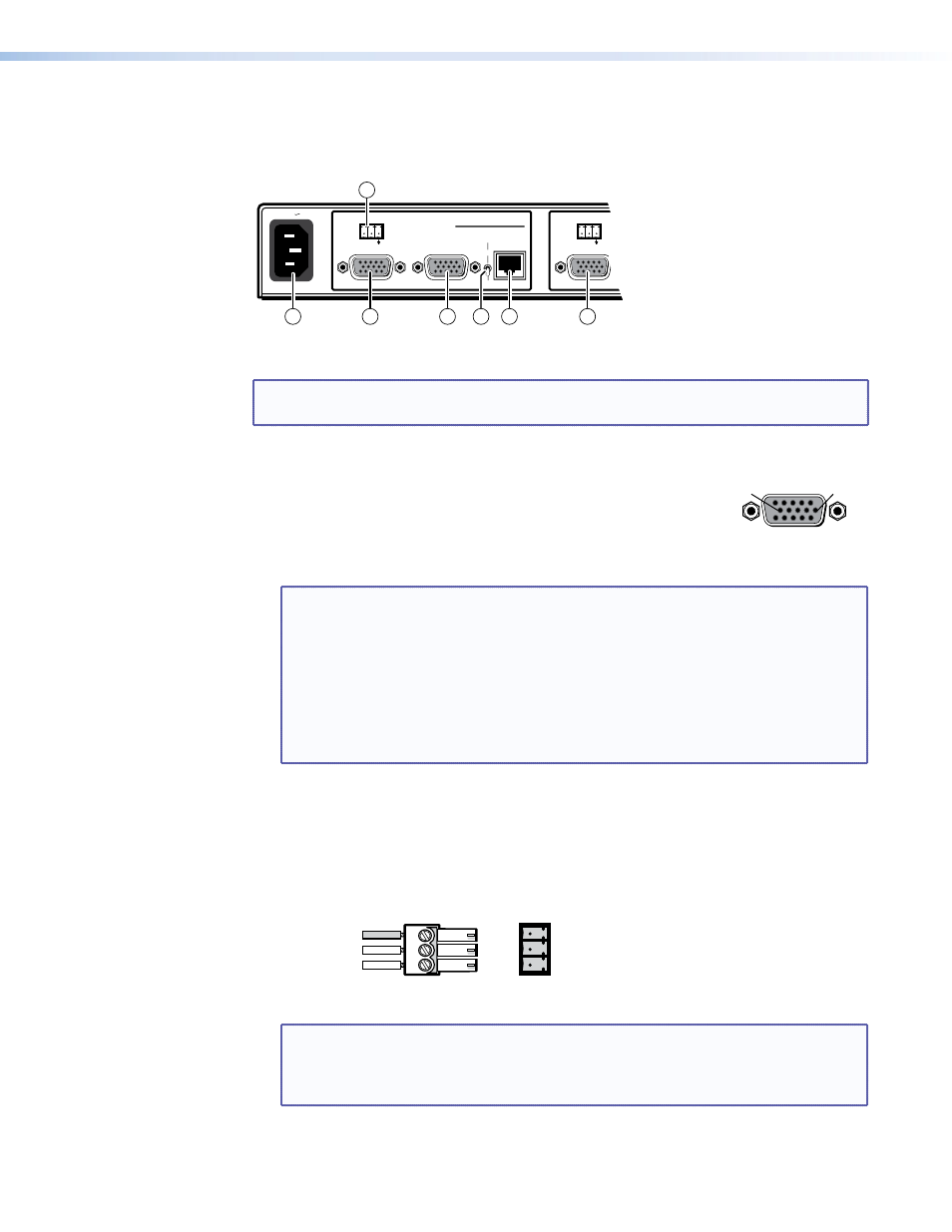
See figure 2 to identify the rear panel connections on the transmitter.
OUTPUT
INPUT
Tx Rx
RS-232
MONITOR
PRE-PEAK
ON
OFF
MTP T 15HD RS 1
INPUT
Tx Rx
RS-232
50/60 Hz
100-240V 0.3A
6
5
1
3
2
4
2
Figure 2.
Transmitter Assembly’s Rear Panel Features
NOTE: There is one item
a
, powering all four transmitters. There are four items
b
through
f
, one for each transmitter.
a
AC power connector — Plug a standard IEC power cord into this connector to connect
the transmitter assembly to a 100 VAC to 240 VAC, 50 to 60 Hz
power source.
b
Input video connector — Connect a computer video source to
this 15-pin HD connector for high resolution video input.
NOTES:
•
Input only sync signals, no video signals, on the sync pins, 13 and 14.
•
For component video, use the R (R-Y) and R return pins (pins 1 and 6), G
(Y) and G return pins (pins 2 and 7), and B (B-Y) and B return pins (pins 3
and 8).
•
For S-video, use the R, R return (C-chroma), G, and G return (Y-luma) pins.
•
For composite video, use the G pin and the associated return pin. For
additional genlocked video signals, use the R, B, and associated return
pins.
c
Monitor connector — Connect a video monitor to this 15-pin HD connector for
buffered, high resolution video loop-through.
d
RS-232 connector — Connect a serial communications device to this 3.5 mm, 3-pole
captive screw connector for bidirectional RS-232 communication. Wire the connector as
shown in figure 3.
Ground
Tx
Rx
Gnd
Receive
Transmit
Connected RS-232
Device Pins
MTP
Pins
Figure 3.
RS-232 Connector Wiring
NOTE: By default, the RS-232 portion of the TP link is unidirectional only from the
transmitter to the receiver. If there is only one receiver in a system, a jumper
within the receiver allows the RS-232 communication to be bidirectional (see
the MTP 15HD RS Series User Guide).
5
1
15
11
6
10
Female