Preliminar y – Extron Electronics MLS 406SA User Manual
Page 13
2-
MLS 304 Series, MLS 406 Series • Installation
PRELIMINAR
Y
Ö
MLS 406, MLS 406MA, MLS 406SA audio input 4 (captive screw) — This
input accepts line level audio signals from consumer and professional audio
sources. Consumer devices such as laptops, VCRs, and DVD players typically
output an unbalanced -20 dBV to -10 dBV signal. Professional products such
as mixers and signal processing gear typically output a balanced +4 dBu level
signal. To adjust input levels, see pages 3-5 and 4-10 through 4-11.
Wire the 3.5 mm captive screw connector as shown in the
following illustrations, depending on input signal type.
L
R
L
R
L
R
L
R
Unbalanced Stereo Input
Tip
Sleeve
Tip
Sleeve
Balanced Stereo Input
Tip
Ring
Sleeve (s)
Tip
Ring
(high impedance)
(high impedance)
Unbalanced Mono Input
Tip
Sleeve
Tip
Sleeve
Balanced Mono Input
Tip
Ring
Sleeve (s)
Tip
Ring
(high impedance)
(high impedance)
0.2” (5 mm) max.
The length of exposed wires is critical.
The ideal length is
0.2" (5 mm).
• If the stripped section of wire is
longer than 0.2", the exposed
wires may touch, causing a
short circuit between them.
• If the stripped section of wire is
shorter than 0.2", wires can be
easily pulled out even if tightly
fastened by the captive screws.
Do not tin the wires!
N
After the audio inputs and outputs are connected, see chapter 3 for
instructions on how to adjust the per-input audio sensitivity levels and
optimize audio input and output.
Computer video (and audio) inputs
— MLS 304MA and MLS 304SA inputs
3 and 4; and MLS 406, MLS 406MA, and MLS 406SA inputs 4, 5, and 6, all on
15-pin HD connectors; are individually buffered and provide ID bit
termination. They accept
•
RGB computer video signals (default) or
•
S-video (MLS 406 Series only) or composite video (all models)
For S-video or composite video, the switcher must be configured via RS-232
serial control (SIS commands or control software); see pages 4-4 and 4-10
through 4-11.
For RGB input, connect a standard VGA-style cable from the source computer
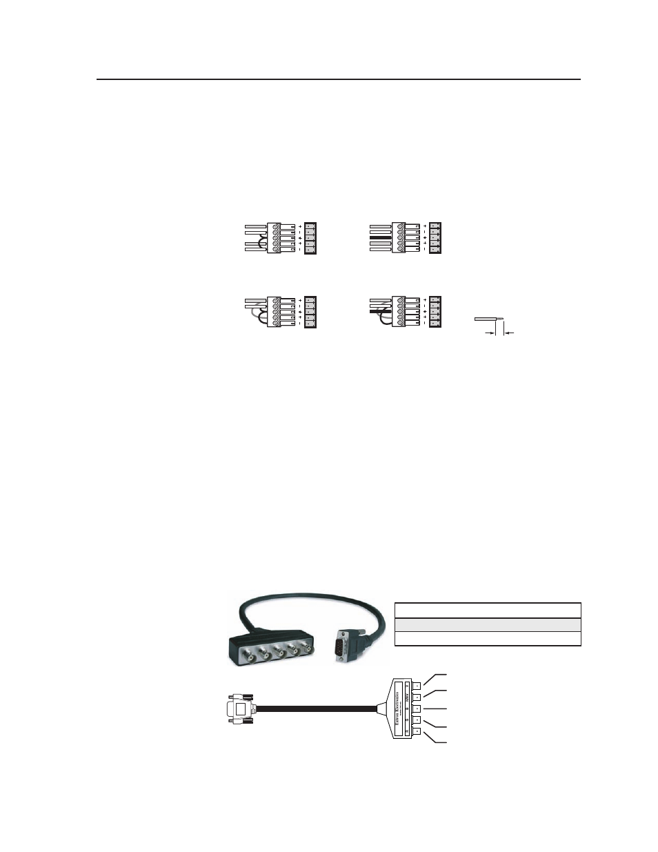
to the desired MLS input. For S-video or composite video input, you may
need to use an adapter cable such as an Extron SY 15HDM-RGBHV cable
(shown below). Connect the video or S-video source to the MLS as follows:
Input Type
Signal (BNC Color) 15-pin HD Pin
S-video
Y (green), C (blue)
2, 3
Composite video
video (red)
1
V = vertical sync
R = red or video
G = green or S-video (Y)
B = blue or S-video (C)
H/HV = horiz. sync
N
Selecting S-video or composite video for these inputs limits the Monitor
Output mode options to Standard Mode.