Preliminar y, Installation, Rear panels and cabling – Extron Electronics MLS 406SA User Manual
Page 12: Power, input, and control connections, Power connection, A/v input connections, Tip (+) sleeve ( ) audio rca connector color_2.eps
MLS 304 Series, MLS 406 Series • Installation
2-
Installation
PRELIMINAR
Y
Rear Panels and Cabling
Power, input, and control connections
AUDIO INPUTS
LINE LEVEL
MONO
AUDIO
AUDIO
AUX/MIX
ADJUST
-42dB
TO
+24dB
L
R
L
R
1
2
INPUTS
OUTPUTS
VIDEO
H
V
B
G
R
1
2
INPUTS
3
4
MONITOR OUT
100-240V
1.0A MAX.
50-60Hz
OUTPUTS
VIDEO
H
V
B
G
R
Y
MONITOR OUT
C
R
L
AUDIO INPUTS
LINE LEVEL
MONO
AUDIO
AUDIO
AUX/MIX
ADJUST
-42dB
TO
+24dB
L
R
L
R
L
R
1
2
3
INPUTS
OUTPUTS
VIDEO
H
V
B
G
R
Y
1
2
3
INPUTS
MONITOR OUT
4
5
6
C
100-240V
1.0A MAX.
50-60Hz
RS-232/MLC/IR
Tx Rx IR
12V
A B C
PREAMP
LINEOUT
AUDIO INPUTS
LINE LEVEL
MONO
AUDIO
AUDIO
AUX/MIX
ADJUST
-42dB
TO
+24dB
L
R
L
R
1
2
OUTPUTS
VIDEO
H
V
B
G
R
3
4
MONITOR OUT
AUDIO INPUTS
AUDIO
AUDIO
L
R
L
R
L
R
1
2
3
INPUTS
4
5
6
LINE LEVEL
MONO
AUX/MIX
ADJUST
-42dB
TO
+24dB
INPUTS
AMPLIFIED OUTPUT 20 WATTS MONO
DIRECT
XFMR
COM
4/8 ohm
100V
70V
AMPLIFIED OUTPUT 20 WATTS MONO
DIRECT
XFMR
COM
4/8 ohm
100V
70V
4
R
L
R
L
RS-232/MLC/IR
Tx Rx IR
12V
A B C
PREAMP
LINEOUT
R
L
R
L
AMPLIFIED OUTPUT
4/8 ohm
RIGHT
LEFT
STEREO OR DUAL MONO
C
LA
S
S
2
W
IR
IN
G
R
L
RS-232/MLC/IR
Tx Rx IR
12V
A B C
PREAMP
LINEOUT
4
R
L
R
L
RS-232/MLC/IR
Tx Rx IR
12V
A B C
PREAMP
LINEOUT
R
L
R
L
2
4
5
3a
3b
6
1
7
8
9
10
11
12
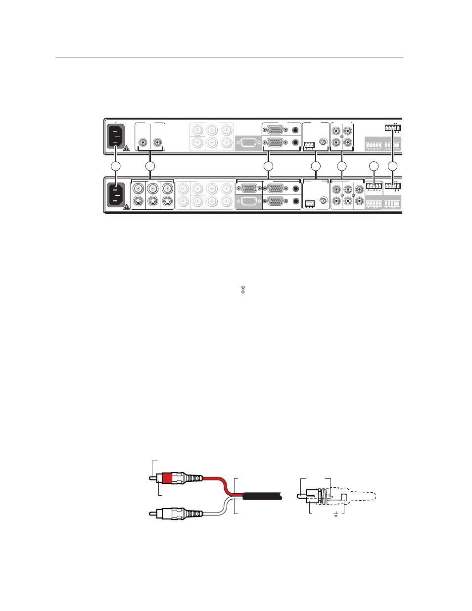
MLS 304MA and MLS 304 SA Rear Panel
MLS 406, MLS 406MA, and MLS 406SA Rear Panel
MLS 304MA Rear Panel
MLS 406MA Rear Panel
MLS 406SA Rear Panel
(amplifier output)
N
The MA and SA models differ only by amplifier output type and connection.
All other A/V, power, and control connections are the same.
Power connection
a
AC power connector — Plug a standard IEC power cord into this connector to
connect the switcher to a 100 to 240 VAC, 50 Hz or 60 Hz power source.
The front panel power LED ( ) lights while the MLS is receiving power.
A/V input connections
b
B
Video inputs —
MLS 304MA MLS 304SA:
connect a composite video source device to each of
these female RCA (tip-ring) connectors for video inputs 1 and 2.
MLS 406
, MLS 406MA, MLS 406SA: connect either an S-video source (using
the 4-pin mini DIN connector) or a composite video source (using the
BNC connector) for input 1, 2, or 3.
Ñ
RCA audio inputs — These audio inputs correspond to the like-numbered
video inputs. These inputs accept line level audio signals from consumer
and professional audio sources. Consumer devices such as PCs, VCRs, and
DVD players typically output an unbalanced -20 dBV to -10 dBVsignal.
Professional products such as mixers and signal processing gear typically
output a balanced 0 dBu to +4 dBu (+6 dBV) level signal.
To adjust input levels, see pages 3-5 and 4-10 through 4-11.
Connect an unbalanced stereo audio source to each pair of RCA jacks. Use
the red sheathed cable/connector for the right channel, and use the white
sheathed cable/connector for the left channel as shown below.
Sleeve (Gnd )
Tip (+)
Sleeve ( )
Audio RCA connector color_2.eps
Right Channel
(Red Jacket)
Left Channel
(White Jacket)
Tip (Signal)
Wiring RCA connectors for unbalanced stereo audio input
N
After the audio inputs and outputs are connected, see chapter 3 for
instructions on how to adjust the per-input audio input levels and optimize
audio input and output.