Installation and operation, cont’d – Extron Electronics MPA 181T User Guide User Manual
Page 12
MPA 181T • Installation and Operation
MPA 181T • Installation and Operation
Installation and operation, cont’d
4
Balanced or unbalanced audio input connector
— Marked “L”
and “R”, this 3.5 mm captive screw input is for bare wire,
balanced or unbalanced audio signals.
Unbalanced Output
Tip
See Caution
Sleeve (s)
Tip
See Caution
Balanced Output
Tip
Ring
Sleeve (s)
Tip
Ring
LR
AU
D
IO
AU
D
IO
LR
Figure 2-7 — 3.5 mm captive screw audio input
connector wiring
CAUTION
Connect the sleeves to ground (Gnd). Connecting
the sleeve to a negative (-) terminal will damage the
audio output circuits.
Remote control
5
Remote input connector
— An optional 5-pin, captive screw
connector that allows a wall mounted audio controller or
MediaLink product to remotely control volume and mute levels
for the MPA 181T unit.
For more information on using the remote input connector, see
Chapter 3, Remote Operation.
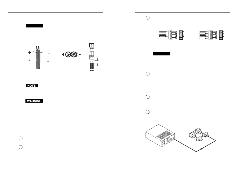
6
Output impedance toggle switch
— A switch to toggle between
a 70 volt or 4/8 ohm output.
Audio output
7
Speaker connector
— This 4-pin, 5 mm captive screw connector
is used to connect the amplifier to the speakers.
PO
W
ER
12
V
3A
M
AX
OUTP
UT
S
4/8
Oh
ms
INP
UT
S
70
V
CO
M
70V
RE
MO
TE
(M
ON
O)
(M
ON
O)
L
R
10
V
LIS
TE
D
1T
23
I.T
.E
.
VO
L/M
UT
E
L
MP
A 1
81T
R
C
C
US
US
Extron
SI 3CT LP
70V/100V/8 ohm
Ceiling Speakers
Extron
MPA 181T
Mini Power
Amplifier (70V)
Figure 2-8 — Typical speaker connection
2-9
To verify the polarity before connection, plug in the power
supply with no load and check the output with a voltmeter.
CAUTION
When connecting the power supply, voltage polarity
is extremely important. Applying power with
incorrect voltage polarity could damage the power
supply and the interface. Identify the power cord
negative lead by the ridges on the side of the cord.
Power Supply
Output Cord
Captive Screw
Connector
0.2” (5 mm) MAX
SECTION A–A
Ridges
Smooth
A A
Figure 2-6 — Power connector wiring
Do not tin the stripped power supply leads before
installing the captive screw connector. Tinned wires are
not as secure in the captive screw connectors and could
pull out.
The two power cord wires must be kept separate
while the power supply is plugged in. Remove
power before continuing.
Audio inputs
There are three choices of input connectors (RCA, 3.5 mm
stereo, and captive screw) available on the rear panel for
adapter-free connections.
All inputs are actively mixed together then summed into a
mono signal.
2
RCA input connector
— Plug an RCA audio source to this line
level input.
3
3.5 mm stereo input
— Plug a 3.5 mm audio micro cable into
this stereo jack.
2-8