Iss 506 • setup guide (continued), Step 3 — video outputs, Step 4 — audio – Extron Electronics ISS 506 Setup Guide User Manual
Page 2: Step 5 — serial ports, Config
2
c.
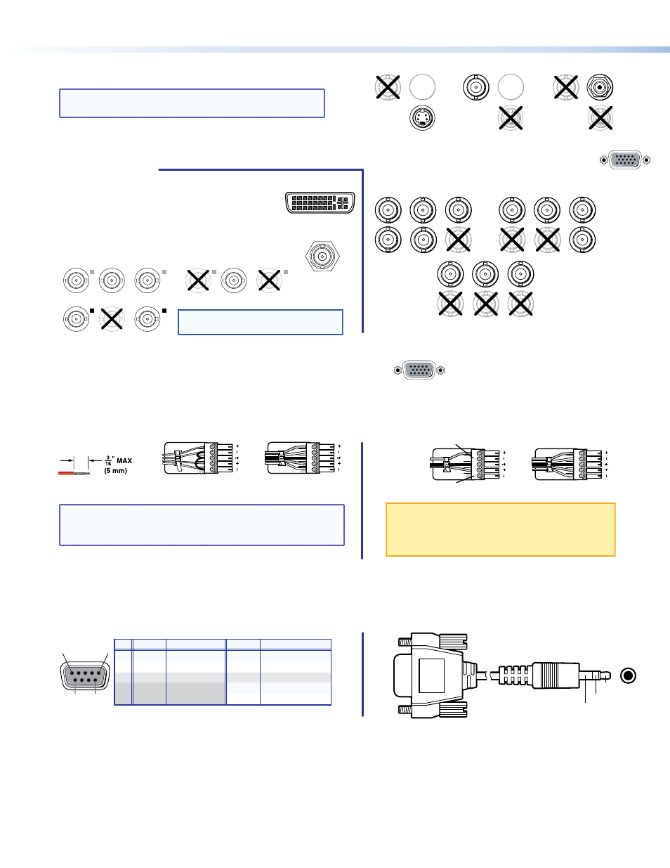
Input 6 — Connect S-video, composite video or SDI/HD-SDI video
to this female 4-pin mini-DIN or BNC connector as shown at right.
NOTE: The SDI or HD-SDI video input is available only
if the optional SDI input board is installed.
Step 3 — Video outputs
a.
Program outputs — Connect video devices to the 15-pin HD output female connector (shown at right) and
the BNC connectors (shown below).
b.
If an optional program output board is installed
(see the ISS 506 User Guide, available at
www.extron.com
), connect a DVI-D (shown
at right), 3G/HD-SDI (shown below right), or
low resolution device (scan converted output),
shown below, to the board.
c.
Preview output — Connect a video device to the 15-pin HD connector.
Step 4 — Audio
a.
Connect up to six stereo or mono audio inputs to the 5-pole captive screw input connectors.
b.
Connect balanced or unbalanced stereo audio or mono audio devices to one or both of the program captive screw output
connectors and the preview 5-pole captive screw output connector.
NOTE: The Variable Program audio output is adjustable
using the front panel Volume control. The other
audio outputs are not adjustable.
Step 5 — Serial ports
a.
If desired, connect a control system or computer to the rear panel RS-232/RS-422 port, as shown below left.
b.
If desired, connect a control system or computer to the front panel Configuration (RS-232) port. The optional 9-pin D to 2.5 mm
mini jack TRS RS-232 cable, part number 70-335-01, can be used for this connection, as shown below right.
CONFIG
Sleeve (Gnd)
Ring
Tip
RS-232 Function
Pin
Function
2
3
5
7
8
TX
RX
Gnd
—
—
Transmit data
Receive data
Signal ground
Not used
Not used
TX–
RX–
Gnd
RX+
TX+
Transmit data (–)
Receive data (–)
Signal ground
Receive data (+)
Transmit data (+)
RS-422
RS232/422
1
5
6
9
VID
6
YC
SDI
VID
6
YC
VID
6
YC
SDI
Composite Video
SDI or HD-SDI
S-Video
SDI
Input 6 Configurations
RGBHV
Video
RGBS
Video
RGsB and
Component
Video
S
H
V
G
/Y
R
R-Y
B
/
B-Y
S
H
V
G
/Y
R
R-Y
B
/
B-Y
S
H
V
G
/Y
R
R-Y
B/
B-Y
Program Output Configurations
DVI Video
3G/HD-SDI Video
R-Y/
R
C
Y/
G
VID
B-Y/
B
Y
Component Video
S-Video
R-Y/
R
C
Y/
G
VID
B-Y/
B
Y
Composite Video
R-Y/
R
C
Y/
G
VID
B-Y/
B
Y
Scan Converted Output Configurations
NOTE: The ISS outputs S-video and
composite video simultaneously.
Unbalanced Stereo Input
Balanced Stereo Input
Do not tin the wires!
Tip
Ring
Tip
Ring
LR
Sleeves
Tip
Sleeve
Sleeve
Tip
LR
Unbalanced Stereo Output
Balanced Stereo Output
Tip
NO GROUND HERE
NO GROUND HERE
Tip
LR
Sleeves
Tip
Ring
Tip
Ring
LR
CAUTION: For unbalanced audio, connect the
sleeves to the ground contact. DO
NOT connect the sleeves to the
negative (-) contacts).
ISS 506 • Setup Guide (Continued)