Indications, Switcher setup and indications, Operation – Extron Electronics IR 501 User Manual
Page 3: Sample operations
Indications
IR 501 Small Matrix Remote Control • Operations
4
IR 501 Small Matrix Remote Control • Operations
5
Switcher Setup and Indications
N
For MAV A/V switchers, the
switcher’s IR receiver is disabled by
default and must be enabled to use
the IR Remote Control. Refer to
the
MAV 44 / 48 / 84 / 88 Series
Matrix Switchers manual
to enable the IR receiver.
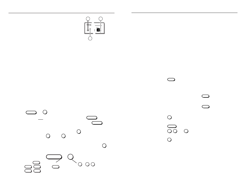
It is not the purpose of this manual to
define the switcher’s front panel indications, but two of the switcher’s
LEDs indicate operation by the IR 501 remote control (figure 3).
Other indications are identified where appropriate in the “Operations”
section.
h
Infrared remote sensor — This sensor receives infrared (IR)
signals from the optional IR 501 small matrix universal remote
control. The IR remote control must be pointed within 30 degrees
of this sensor for best results.
i
Power LED — This LED blinks off and on to indicate that an IR
signal has been received.
j
Audio Setup LED (A/V switchers only) — This LED lights for a
second when an improper or unexpected IR command is received.
Operation
Most functions can be performed by pushing a similar sequence of
{function}
and
I/O
buttons (figure 4).
•
Video and audio operations require only one
{function}
button.
•
Video-only or audio-only operations require two
{function}
buttons
(one to identify the function, one to identify video or audio).
•
For numbers higher than 9, press the
+10
button and then press the
applicable
0
through
9
button.
•
Creating a set of ties requires at least two sequences (the input
sequence, one or more output sequence[s]) and then the
ENTER
button.
{function}
I/O
3
+ 2
(s)
+
number(s)
(Such as
(for 12)
, or
.)
+10
(Such as
INPUT
,
(video only), or
+
MUTE
VIDEO
INPUT
INPUT
(audio only).
+ AUDIO
(video
and audio),
Figure 4 — Button sequence
Sample Operations
N
The following examples show operations with specific input, out-
put, and preset numbers. Use your own numbers as desired.
N
The switcher’s Power LED flashes whenever the switcher receives
an IR command. Other switcher indications are identified in the
following examples where appropriate. For detailed descriptions of
how the switcher indicates ties and presets, refer to the appropriate
matrix switcher’s manual.
N
Many operations require a sequence of IR commands. When
multiple IR commands are required, the entire sequence must be
completed within 5 seconds. If a valid sequence is not completed
within 5 seconds, the switcher times out and discards all received
IR commands
Create ties
By default, you create video and audio (audio follow) ties using the
IR 501. By pushing one extra button you can create audio-breakaway
ties.
1.
Press the
INPUT
button to specify an input selection. The
switcher’s Video LED and Audio LED light.
N
To create video and audio ties, skip to step 3.
2.
Specify video or audio:
a
.
For video-only tie(s)
, press the
VIDEO
button to specify a
video selection. The switcher’s Video LED remains lit and
the Audio LED goes off.
b
.
For audio-only tie(s)
, press the
AUDIO
button to specify an
audio selection. The switcher’s Audio LED remains lit and
the Video LED goes off.
3.
Press the
5
button to select input 5. The switcher’s Input 5 LED
lights.
4.
Press the
OUTPUT
button to specify output selection(s).
5.
Press the
3
,
4
, and
8
buttons to select outputs 3, 4, and 8.
The switcher’s selected Output LEDs blink.
6.
Press the
ENTER
button to create the tie. The switcher displays
the ties as described in the switcher’s manual.
Figure 3 — Switcher
features
MAV SERIES
AV MATRIX SWITCHER
I/O
AUDIO SETUP
IR
+dB
-dB
10
8
9