Installation and operation, cont’d, Transmitted signal cabling – Extron Electronics CAT 5 Transmitters User Manual
Page 10
CAT 5 Transmitters • Installation and Operation
CAT 5 Transmitters • Installation and Operation
Installation and Operation, cont’d
2-8
R
G
B
H/HV
V
For composite video, use the R, G, and/or B BNC.
R
-or-
-or-
G
B
H/HV
V
Transmitted signal cabling
Do not connect this device to a computer data or
telecommunications network
RJ-45 termination must comply with the TIA/EIA
T 568A
wiring standards for all connections.
9
RGB video transmission connector —
Attach one end of a
CAT 5 UTP cable to this RJ-45 female connector. Attach the
other end to an Extron CAT 5 BNC receiver.
10
Composite video transmission connector —
Attach one end of
a CAT 5 UTP cable to this RJ-45 female connector. Attach the
other end to an Extron CAT 5 composite video receiver.
Termination of CAT 5 cable
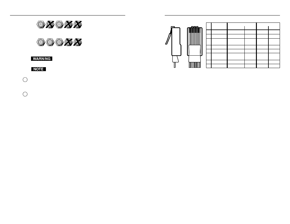
Figure 2-8 details the recommended termination of CAT 5 cables
in accordance with the TIA/EIA T 568A wiring standards.
Cable testing
To ensure proper cable termination, each transmission cable
system should be tested. Testing the cable from the RJ-45
connections at the transmitter and receiver gives the most
accurate indications of cable problems.
There are two varieties of cable runs: simple runs, in which a
single cable is terminated only at the transmitter and receiver,
and complex runs, which can include patch bays and multiple
terminations and lengths of cable. In either case, the entire
cabling system should be tested.
A complete test measures cable length and tests the wire map,
attenuation, NEXT, PSNEXT, ELFEXT, PSELFEXT, return loss,
ACR and PSARC. All of these tests are critical for digital data
transfer. While all of these tests are important indicators of the
quality of the cable termination, the most critical testing
parameters for video transfer are wire map (T-568-A
termination) and pair length measurements. The largest
concern is equalization of skew between cable pairs. Cable
systems of 300 feet or less should exhibit no transmission
problems if they pass at least CAT 5e or preferably CAT 6-D5
channel certification testing.
Clip Down
Side
1 2 3 4 5 6 7 8
1 2 3 4 5 6 7 8
Pin
Wire color
RGB video and audio
AV Video and audio
Signal
Level
Signal
Level
1 White-green
Red/V. sync+
±0.35V
Video+
+0.35V
2
Green
Red/V. sync-
±0.35V
Video-
-0.35V
3
White-orange
Audio &
power
+15V with
±0.5 V
Power+
+15V
4
Blue
Green+
+0.35V
Reserved None
5
White-blue
Green-
-0.35V
Reserved None
6
Orange
Audio &
power
±0.5 V
Power-
0V
7
White-brown
Blue/H. sync+ ±0.35V
Audio+
±0.5 V
8 Brown
Blue/H. sync-
±0.35V
Audio-
±0.5 V
Figure 2-8 — CAT 5 cable termination
The Microtest OMNI SCANNER 2 performs comprehensive
certification testing to the proposed CAT 6 standards. Other
manufacturers also make testing equipment. The tests include
advanced diagnostics for troubleshooting the cause and location
of many cable and termination problems. For simple
installation testing, the Microtest MICRO SCANNER PRO tests
wire map and cable length, including individual cable pair
length.
Equalizing pair skew
The manufacturing process for UTP cable leads to a condition
called pair skew. Skew exists between pairs when the physical
length of one wire pair is different from another. As the
transmission cable length increases, the amount of skew
increases. Skew affects the displayed image when the
differential length between wire pairs exceeds 2 feet, causing the
timing of the red, green, and blue video signals to appear out of
alignment (horizontal registration errors). A white vertical line
on a black field can appear as individual red, green, and blue
lines that are close together; the signal transmitted on the
shortest wire pair leads the other colors and appears to the left
on the display.
UTP cable test equipment measures and reports wire pair
length. The report on the various pair lengths can be used in
equalizing pair skew. The nominal velocity of propagation
(NVP — the speed at which the signal travels on the
transmission line, measured as a percentage of the speed of
light) is very close to that of conventional coaxial cable. The
similarity in NVP means that an additional length of coax equal
to the length of pair skew, placed on the receiver’s output,
equalizes the effects of pair skew (figure 2-9).
2-9