Installation and operation, 1extron • audio/video distribution amplifiers – Extron Electronics SVDA 6A MX User Manual
Page 3
1
Extron • Audio/Video Distribution Amplifiers
Left
Right
Gnd
Left
Right
Gnd
Tip
Sleeve(s)
Tip
Unbalanced Output (high impedance)
NO Sleeve here!
Left
Right
Gnd
Tip
Tip
Balanced Input (high impedance)
Ring
Tip
Sleeve(s)
Ring
Tip
Left
Right
Gnd
Ring
Tip
Sleeve(s)
Ring
Tip
Sleeve
Sleeve
Unbalanced Input (high impedance)
Left
Right
Gnd
Ring
Tip
Ring
Tip
Balanced Output (high impedance)
600 ohms
600 ohms
Balanced Input (600 ohms))
Left
Right
Gnd
Ring
Tip
Ring
Tip
Balanced Output (600 ohms)
Sleeve(s)
Sleeve(s)
I
NPUTS
O
UTPUTS
NO Sleeve here!
Tip
Sleeve
Ring (-)
Tip (+)
Sleeve
2
4
2
2
One input, six output Composite Video Distribution Amplifier
One input, six output S-Video Distribution Amplifier
One input, six output Stereo Audio Distribution Amplifier
Rack mountable in a 1U half-width enclosure
Rack mountable in a 1U full-width enclosure
AVDA 6 MX
P/N 60-201-01
AVDA 6 MX DUAL
P/N 60-201-02
CVDA 6 MX
P/N 60-202-01
CVDA 6 MX DUAL
P/N 60-202-02
CVDA 6 MX QUAD
P/N 60-202-03
SADA 6 MX
P/N 60-203-01
SADA 6 MX DUAL
P/N 60-203-02
SADA 6 MX QUAD
P/N 60-203-03
SVDA 6 MX
P/N 60-204-01
SVDA 6A MX
P/N 60-353-01
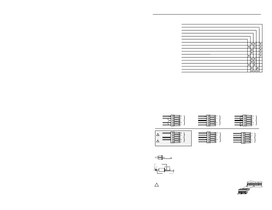
Models and Features
Extron's Audio/
Video Distribution
Amplifier models
include two or
more of the
features listed at
the top of the
table to the right.
A "•",
2 or 4 is used in
the table to
indicate which
features apply to
a particular
model and how
many, if more than one. For example, the model SVDA 6 MX DUAL has 2 - one
input, six output stereo audio distribution amplifiers. All models are housed in metal
enclosures and include 100-240 volt universal switchable power supplies.
Installing Captive Screw type Audio Connectors
Three methods of wiring the audio connectors for input and output are listed and
shown below. Input examples are across the top, output examples are below them.
• Unbalanced High Impedance (High Z) Stereo Tip, Ring, Ground (Left & Right)
• Balanced High Impedance (High Z) Stereo Tip, Ring (Left & Right)
• Balanced 600 ý input Impedance Stereo Tip, Ring (Left & Right)
Use the picture to the left when making connections for the Audio
Distribution Amplifier from existing audio cables. The round audio
connectors are shown with the top one (tip and sleeve only) for
unbalanced audio and the bottom one (tip, ring and sleeve) for
balanced audio. The "ring", "tip" and "sleeve" markings are also used
on the captive screw audio connector diagrams above. Together,
these examples may be used as a guide for making audio cables.
___ If using the Unbalanced Output example shown above
(shaded background), connect the sleeve(s) to
L
R
2
3
L
R
Installation and Operation