Service instructions – Bell & Gossett V58912B PSH Primary-Secondary Header Flanged & Threaded Connections User Manual
Page 2
5. Reassemble the two side sections, fitting the lower cap
into one of the two sections and then connecting the other.
6. Finish the assembly with the adhesive tape provided in the
box.
7. Complete with the two black head covers.
8. Fit the automatic air vent and the drain valve.
Recommended sealant: Superclear mastic.
SERVICE INSTRUCTIONS
There is no service required for the PSH.
CAUTION: Corrosion or leakage of the PSH can cause
damage or injury. Periodically inspect the PSH for
signs of leakage or corrosion. If noted, PSH must be
replaced. Failure to follow these instructions could result in
property damage and/or moderate personal injury.
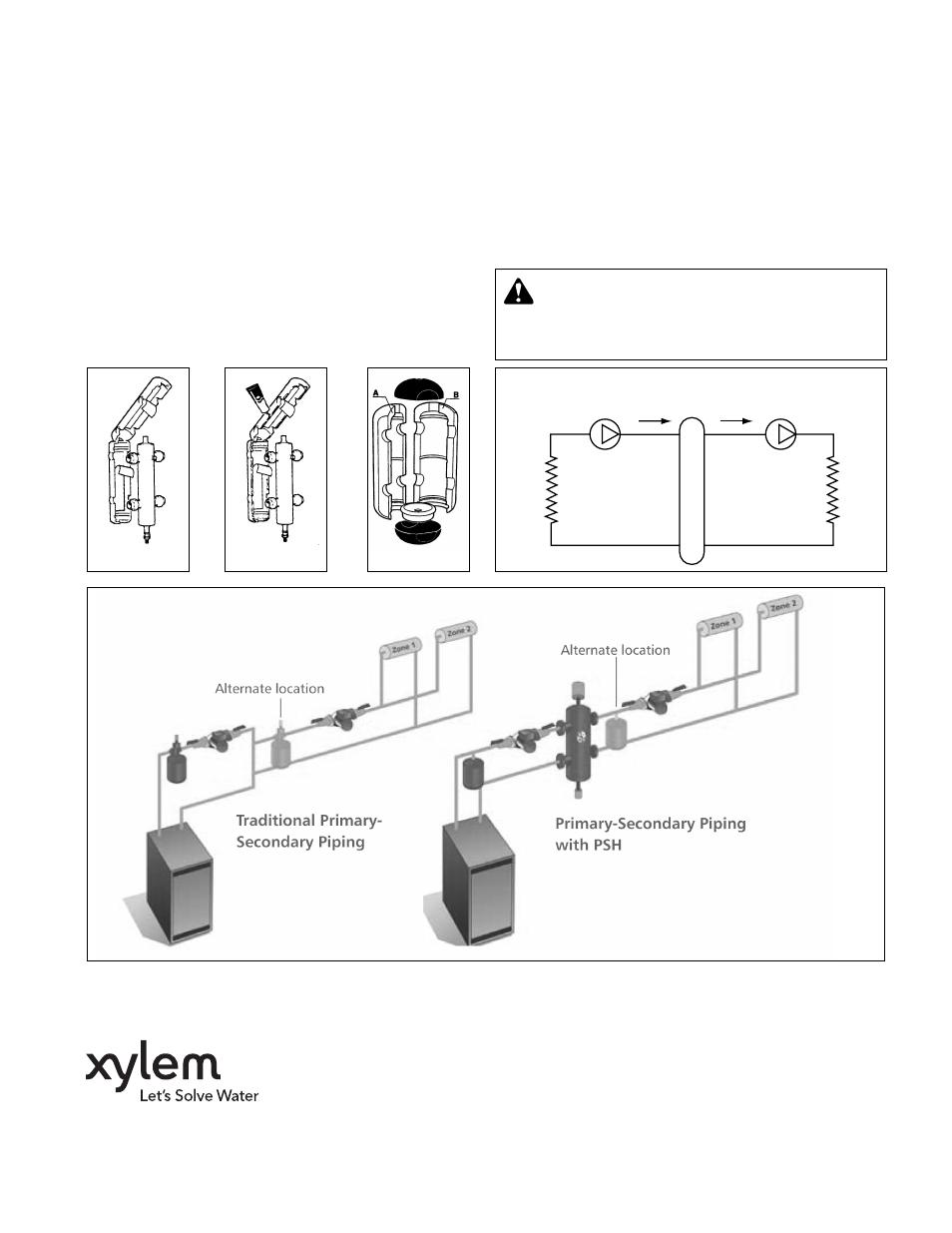
Procedure for installation and insulation
assembly on threaded models
1. Remove the protective strip from the adhesive surface. Re-
close the shells (See Illustration A).
2. If the hydraulic separator is used with chilled water spread
a thin layer of sealant on the edge of the insulation and
wait until the solvent evaporates (10 minutes approx.) and
then close it again (See Illustration B).
Procedure for installation and insulation
assembly on flanged models (up to 4")
1. Remove the two black head covers at the ends.
2. Open the two side sections and the lower cap.
3. Install the separator in the system.
4. Use the tape provided on insulation.
Illustration A
Illustration B
Illustration C
secondary
circuit
primary
circuit
Primary
Circuit
Flow
Secondary
Circuit
Flow
Xylem Inc.
8200 N. Austin Avenue
Morton Grove, Illinois 60053
Phone: (847) 966-3700
Fax: (847) 965-8379
www.xyleminc.com/brands/bellgossett
Bell & Gossett is a trademark of Xylem Inc. or one of its subsidiaries.
© 2012 Xylem Inc. V58912B May 2012