Coupler alignment – Bell & Gossett Series 80®-PF Type Pumps User Manual
Page 3
COUPLER ALIGNMENT
All alignment should be done by moving or shimming the
motor only. Adjustments in one direction may alter alignment
in another. Therefore, check alignment in all directions after a
correction is made. Black rubber sleeves have different
horsepower load ratings then orange Hytrel sleeves, they
should not be interchanged.
Standard Sleeve Type Coupler with Black Rubber Sleeve
Before aligning the coupler, make sure there is at least
1
/
8
" end
clearance between the sleeve and the two coupler halves.
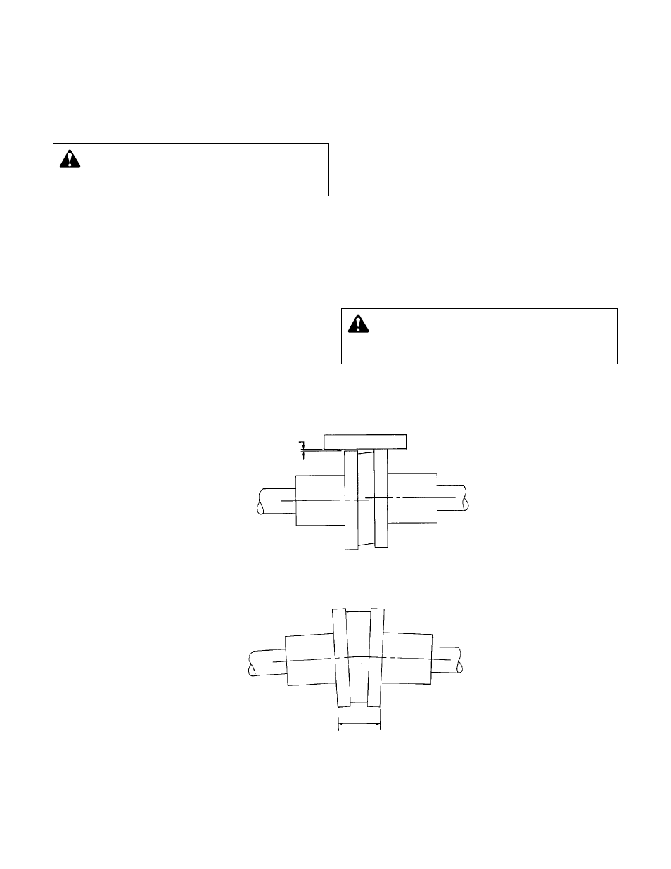
1. Check angular misalignment using a micrometer or caliper.
Measure from the outside face of one flange to the outside
face of the opposite flange at four points 90° apart. Refer to
figure 4. DO NOT ROTATE COUPLER. Misalignment up to
1
/
64
" per inch of coupler radius is permissible.
2. At four points 90° apart (DO NOT ROTATE COUPLER),
measure the parallel coupler misalignment by laying a
straight edge across one coupler half and measuring the
gap between the straight edge and opposite coupler half.
Up to a
1
/
64
" gap is permissible. Refer to figure 3.
For Fine Alignment, Orange Hytrel Sleeves,
3500 RPM Operation, or All Other Coupler Types
Use a dial indicator when greater alignment accuracy is
required. Use the following alignment tolerances unless speci-
fied otherwise by the coupler manufacturer. On sleeve type
couplers make sure there is at least
1
/
8
" end clearance
between the sleeve and the two coupler halves.
1. To check angular misalignment, mount the dial indicator
base to one coupler half or shaft, and position the dial indi-
cator button on the front or rear face of the opposite cou-
pler half. Set the dial to zero. Rotate both coupler halves
together, making sure the indicator button always indi-
cates off the same spot. Misalignment values within 0.004"
TIR per inch of coupler radius are permissible.
2. To check parallel misalignment, mount the dial indicator
base to one coupler half, or shaft, and position the dial indi-
cator button on the outside diameter of the opposite cou-
pler half. Set the dial to zero. Rotate both coupler halves
together, making sure the indicator button always indi-
cates off the same spot. Misalignment within 0.004" TIR is
permissible.
3
ANGULAR ALIGNMENT CHECK
FIGURE 4
AMOUNT OF
PARALLEL
MISALIGNMENT
STRAIGHT EDGE
PARALLEL ALIGNMENT CHECK
FIGURE 3
DISTANCES ACROSS
COUPLER FLANGES
SHOULD BE EQUAL
(CHECK 4 PLACES)
WARNING: ROTATING COMPONENT HAZARD
Do not operate pump without all guards in place.
Failure to follow these instructions could result in serious per-
sonal injury or death, and property damage.
WARNING: UNEXPECTED STARTUP HAZARD
Disconnect and lockout power before servicing.
Failure to follow these instructions could result in serious
personal injury or death, or property damage.