Bell & Gossett Series 80®-PF Type Pumps User Manual
Page 2
For 1531 and Series 80 pumps:
Install motor foot capscrews (1531 only) and tighten. Install
drain plug and close drain valve.
For 1510 pumps:
Install support foot capscrews and tighten. Install coupler and
align per instructions on page 3. Install coupler guard and
drain plug. Close drain valve.
14. Open isolation valves and inspect pump for leaks. If not
leaking return pump to service.
NOTE: Before starting pump, back off packing gland nuts or
screws until glands are loose. Re-tighten with fingers until
glands are just snug against the first packing ring. After pump
is running at first start, water may run freely from packing. This
is normal and should be allowed to continue for a period of
time before further tightening of the glands. Take up gland
bolts uniformly, one flat at a time.
An adequate leakage rate is not one single value for all pumps
and installations, but is the amount required to provide ade-
quate cooling and lubrication. The required leakage will be
largely influenced by operating pressure, fluid temperature,
shaft speed, etc.
For fluid temperatures in the range of 32° to 190°F, average
leakage rates of 60 to 80 drops per minute are recommended.
However, each individual pump and installation will have
unique operating conditions that will result in broadly variable
leakage rate requirements.
At fluid operating temperatures near the upper limit of 190°F,
the maximum temperature rise of the leakage is particularly
important. A packed pump should never operate with steam
forming on the gland. This necessarily limits the temperature
rise to a maximum of about 20°F. If the formation of steam
persists at higher leakage rates, cooling water must be pro-
vided by means of an external supply, or a heat exchanger
used to cool the by-pass flush.
WARNING: Rotating Component Hazard
Do not operate pump without all guards in place.
Failure to follow these instructions could result in serious
personal injury, death and/or property damage.
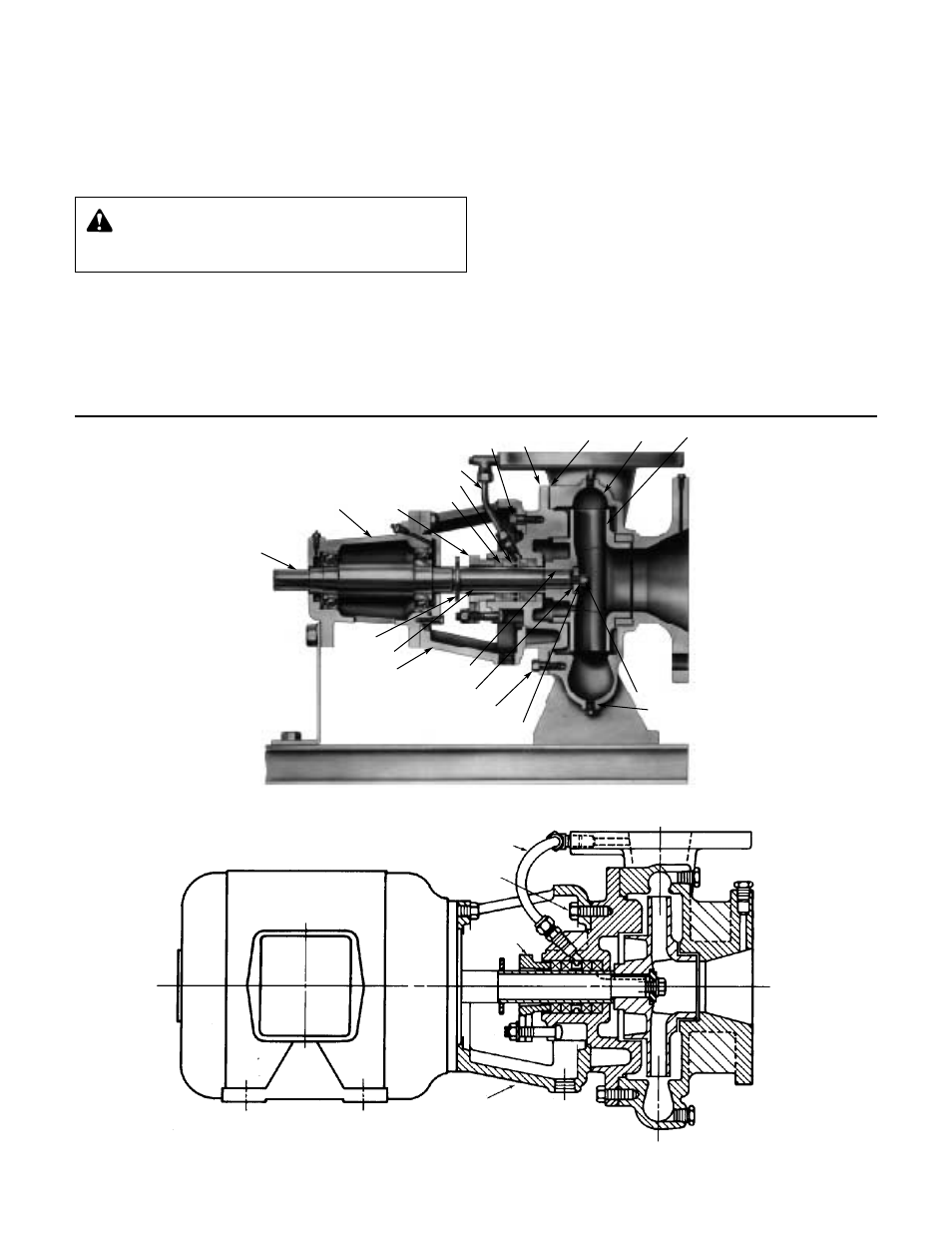
FIGURE 1
FIGURE 2
1510-PF PUMP
1531-PF PUMP
FLUSHING TUBE
COVER PLATE
CAPSCREW
PACKING
GLAND
BRACKET
NOTE: Series 80-PF pump constructed similarly, but mounted vertically.
2
IMPELLER
VOLUTE
VOLUTE
GASKET
COVER-
PLATE
COVERPLATE
CAPSCREWS
FLUSHING
TUBE
LANTERN
RING
PACKING
PACKING
GLAND
BEARING
FRAME
SHAFT
SLINGER
SHAFT
SLEEVE
BRACKET
IMPELLER
KEY
IMPELLER
W
ASHER
VOLUTE
CAPSCREWS
IMPELLER
LOCK
WASHER
IMPELLER
CAPSCREW
DRAIN PLUG