Bell & Gossett P58725B Series 1535C Close Coupled Centrifugal Pump User Manual
Page 5
5
REPLACEMENT PROCEDURE
With motor removed from the system, use the following
instructions to facilitate the replacement.
1. Use a strap wrench or rag to prevent the impeller from
turning with one hand and loosen the impeller nut with the
other.
2. Lift the spring retainer and the seal spring from the shaft.
Remove the compression ring from the seal collar by
inserting a small screwdriver underneath the ring and care-
fully applying an upward prying force. Remove the ring,
collar and the remaining seal components from the shaft.
NOTE: Seal assembly consist(s) of a stationary seal insert
and rotating seal assembly. Each of these components
must be replaced when replacing the mechanical
seal. NEVER REPLACE INDIVIDUAL COMPONENTS
SEPARATELY.
3. Using a clean, lint free rag, remove any debris that may
have accumulated on the seal recess.
4. Place the new seat retainer in the bracket seal recess.
Seat the thin rubber seat gasket in the recess and set the
ceramic seat insert atop the gasket. The ceramic has a top
side and bottom side. The bottom is identifiable by its
slightly recessed grooves. These grooves should face
downward toward the rubber gasket (gear gasket).
5. Lubricate the rubber bellows with soapy water. The entire
rotating seal assembly, which includes the carbon seal
ring, rubber bellows, seal ring retainer and compression
ring, is to be pushed onto the shaft as one unit. Do not
attempt to assemble the seal by placing the components
on the shaft individually. The notches in the seal ring
retainer should be aligned with the recesses found on each
side of the seal ring (rotating ring).
6. Press the rotating seal assembly on the shaft until the
carbon seal ring (rotating ring) makes contact with the
ceramic seat. Press down tightly. A screwdriver can be
used at several points along its periphery to provide a tight
and even fit. Press with the screwdriver – do not tap.
Tapping on the seal may break the ceramic or carbon
insert.
7. Place the seal spring and spring retainer on the shaft.
Next, place the impeller and lock washer. Thread the
impeller nut to the shaft and tighten to 17-22 ft.-lbs. Do
not overtighten.
8. Clean the pump body of excess debris. Place a new
gasket on the pump body; ensure that it sits flush against
the gasket surface.
9. Replace the motor by inserting the impeller in the pump
body and evenly tighten the eight capscrews.
10. Refer to the WIRING INSTRUCTIONS on the motor name-
plate or inside the conduit cover.
11. Follow the OPERATIONAL INSTRUCTIONS in this manual
to 1) check the PH of the system water, 2) to check the
rotation of the pump, and 3) to prime the pump and sys-
tem prior to starting.
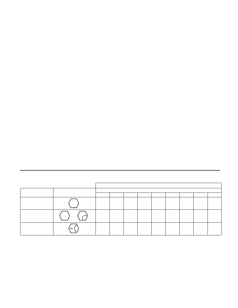
CAPSCREW TORQUE (FOOT-POUND)
CAPSCREW
HEAD
CAPSCREW DIAMETER
TYPE
MARKING
1/4
5/16
3/8
7/16
1/2
5/8
3/4
7/8
1
SAE Grade 2
6
13
25
38
60
120
190
210
300
Brass
Stainless Steel
or
4
10
17
27
42
83
130
200
300
SAE Grade 5
10
20
35
60
90
180
325
525
800