Xylem EPR IM Electric heater-circulator unit EPR (obsolete) User Manual
Page 7
7
Instruction manual Laing Electric heater circulator unit
www.lainginc.com
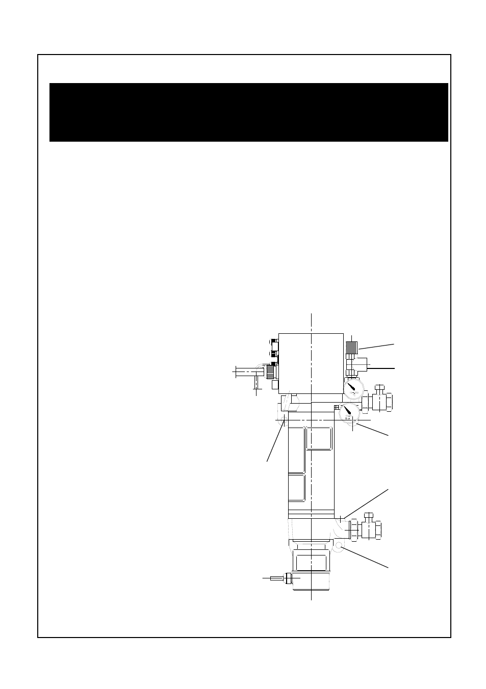
Connection EPR series
Heating
loop return
side
Mounting
eyelet
Connection
for expansi-
on tank
Air vent
Safety relief
valve
Heating
loop feed
side
Mounting
eyelet
Mounting
eyelet
Mounting
For safety reasons, the Electric heater circulator must be mounted on a
fireproof base. In addition, the unit must be installed with the circulator
motor pointing downwards!
The unit must be attached to a flat wall with the help of the mounting eyelets
arranged at the top of the unit and at the pump housing. To avoid noise trans-
fer to the wall, both sides of the mounting eyelets have to be covered with
rubber insulators. The rubber insulators are supplied with the Electric heater
circulator unit and have to be mounted in such a way that no metal contact
exists between the castings and the fastening screw. In addition, no part of
the Electric heater circulator unit - for example the outer shell or the pump
- should be in contact with the wall.
The Electric heater circulator should be mounted at least .4’’ above the
floor to allow replacement of the circulator motor if necessary.
Connection to the feed and return line
The unit is connected to the hea-
ting loop by 1” male threaded fit-
tings. The feed line is at the top of
the unit, the return line at the bot-
tom. The expansion tank should
be connected to the 3/8” port next
to the return line. If the expansion
tank cannot be connected there, it
should be connected somewhere
else in the return line, but not in
the feed line. There are two ˝”
ports at the top of the unit. The
automatic air vent for the heating
circuit is connected to the ˝” port
closest to the wall, the pressure
relief valve to the port in front.
When the Electric heater cir-
culator unit is used solely for floor
heating, the chapter “Important
Notice: Proper connection to a
floor heating system” has to be
observed.