Xylem EPR IM Electric heater-circulator unit EPR (obsolete) User Manual
Page 27
7
Instruction manual Laing Electric heater circulator unit
www.lainginc.com
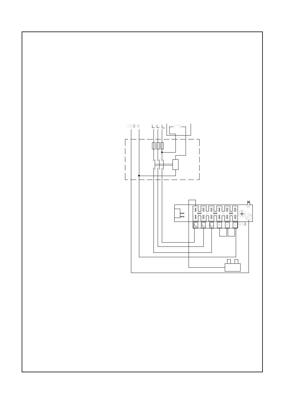
- If all three heating elements should be controlled by a load shedding
device, the unit needs to be connected according to the diagram below.
The diagram shows the connection for 3-phase 400 Volt operation. For
other supply voltages, the corresponding diagram shown under “main
power connection“ should be modified accordingly.
If all three elements are controlled by a load shedding device, a separate
power supply is needed for the control and the circulator pump, so that
these two can operate independent of the load shedding device. This is
necessary since an operation of the unit without deferred pump shutdown
can lead to overheating conditions when the elements are deenergized.
Remove the jumper wire
between Mains terminal
1 and terminal T on the
main switch. Attach the
separate power supply
to terminal T. A separate
switch H1 controls the
operation of pump and
control as well as the con-
tactor for the main power
supply.
If the load shedding de-
vice RR is open but the
switch H1 and the main
switch of the electric hea-
ter cir-culator unit are on,
the control and the pump
will operate. When the
contact RR is closed,
the external contactor
closes and the heating
elements are activated in
accordance with heating
require-ments and selec-
ted heating program.
Wiring schematics for control of all hea-
ting elements by load shedding device