Xylem EPR IM Electric heater-circulator unit EPR (obsolete) User Manual
Page 25
5
Instruction manual Laing Electric heater circulator unit
www.lainginc.com
the relay on the additional printed cir-
cuit board closes and switches the lead
from the hot water heater feed pump to
the control inlet of the Electric heater-
circulator. At the same time the control
lead for the boiler is interrupted, which
ensures that the boiler and the Electric
heater-circulator cannot be working at
the same time.
Each time the boiler control switches
on the hot water heater feed pump,
the Electric heater-circulator is turned
on instead.
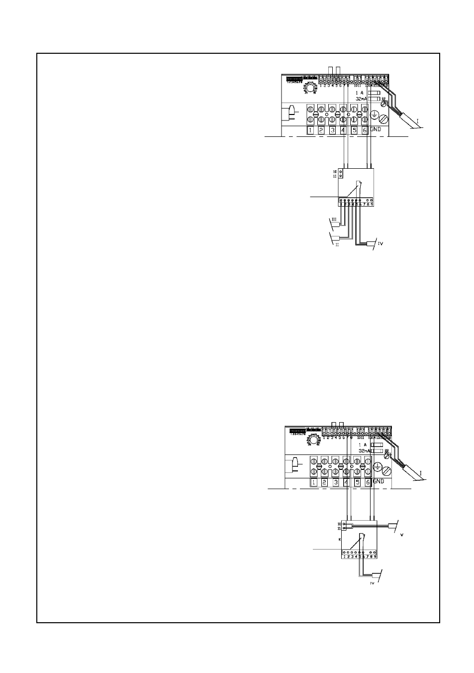
Wiring diagram control method 2
open with EPR on
Control method 2
For this control method it is necessary to install an additional thermostat into
the hot water heater that closes when heat for the hot water heater is needed.
The wiring has to be performed according to the diagram below, whereby
the additional heater thermostat has to be connected to the terminal CS4. A
control lead IV has to be connected to CS3 which prevents the burner from
turning on when the electric heating is active.
As long as the electric heating is switched off via the main switch the relay
Wiring diagram control method 1
on the additional printed circuit board is
de-energized and the control contact of
this relay.
for the burner is closed, so that the
boiler now performs the heating of the
domestic hot water. In this case the
check valve of the Electric heater-cir-
culator is closed and the check valve
for the boiler is open as long as the hot
water heater feed pump is running. As
soon as the main switch of the Electric
heater-circulator is closed, the relais
on the additional printed circuit board
closes and separates the control lead
to the burner. Now the Electric hea-
ter-circulator will be controlled via the
additional thermostat installed within
the hot water heater.
open with EPR on