Palmer - bowlus flume – Xylem Flow Converter 713 User Manual
Page 6
6
Ark6 Diagram 1
Side 1
0
0,05
0,1
0,15
0,
0,5
0,3
0,35
0
50
100
150
00
50
300
350
400
450
500
8"
10"
1"
15"
4"
30"
Q [m
3
/h]
h
a
[m]
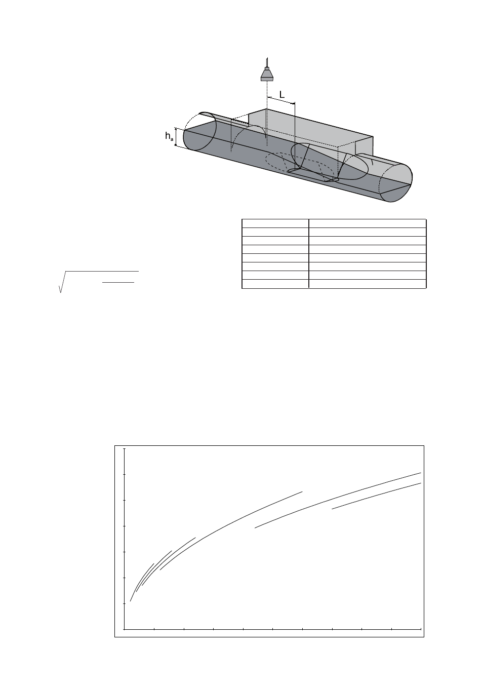
Palmer - Bowlus flume
The Palmer & Bowlus flume is characterized by its circu-
lar connection, which makes it easy to install in pipe-
lines. The flume is aimed at measurement in the scale of
20-100% of the prescribed flow.
where:
h
a
= water level before the narrowing
L = ½ × DN (the nominal diameter of the flume),
measured from the beginning of the meas. section.
No simple flow formulas can be set up for the Palmer
& Bowlus flumes, the formulas are defined individually
for every flume. The Flow formulas are derived from the
continuity equation and Bernoulli’s equation:
Q = g(h
1
- h
) x
where:
A
1
and h
1
= cross section and height in the inlet of the
flume
A
and h
= cross section and height in the outlet of the
flume
For the Palmer & Bowlus flumes with the dimensions 6'',
8", 10", 12", 15", 18'', 21'', 24" and 30", the flow formulas
are defined and incorporated in the flow converter. In
the menu „Programming of flow calculation“ the relevant
flume is chosen.
Q/h diagram for the MJK Palmer & Bowlus flumes, the
height h
a
is shown as a function of the flow Q.
Size D
Max Flow
6'' (DN 150)
35 m
3
/h
8'' (DN 200)
70 m
3
/h
10'' (DN 250)
110 m
3
/h
12'' (DN 315)
200 m
3
/h
15'' (DN 400)
325 m
3
/h
18'' (DN 450)
545 m
3
/h
24'' (DN 600)
1100 m
3
/h
30'' (DN 800)
1750 m
3
/h
Table showing the size of D, and the max. flow for the
Palmer & Bowlus flumes.
A
1
x A
A
1
- A