Parshall flume – Xylem Flow Converter 713 User Manual
Page 5
5
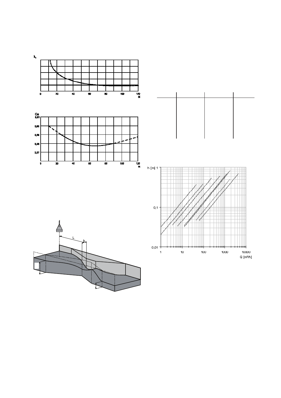
k
h
is set to 0,001 m and is a correction factor.
Ce is the coefficient of discharge (no unit). For determi-
nation of Ce, look at diagram below.
Diagram for determination of k
h
Diagram for determination of Ce
.
Parshall flume
The most common type of flume is the Parshall flume.
The Parshall flume is a standardized Venturi flume.
At free flow, only the level h
a
is measured. The location
of the sensor is important and must be carried out as il-
lustrated in the drawing and the table in the next column.
It is important to have a laminar flow (horizontal stream-
ing calm water with no whirls) at the out- and inlet from
the flume. Upstream the measuring flume, must extend
at least ten times the width of the inlet section of the
flume.
On the outlet side the only demand is that the water
should run freely. This is the case when h
b
≤ 0,7 × h
a
.
The flow is calculated from the formula:
Q = k × h
a
n
where:
Q = flow in m
3
/h
b = width in the measuring flume in[ m]
h
a
= water level before the narrowing in [m]
h
b
= water level in the narrowing in [m]
L = distance to the sensor (use table below)
The factor k and exponent n are constants.
The formula complies to free flow, h
b
max
< 0,7 × h
a max
b
k
n
L
1"
217
1,548
0,24
2"
425
1,548
0,27
3"
630
1,548
0,30
6"
1310
1,574
0,41
9"
1851
1,528
0,58
12"
2407
1,519
0,89
24"
5142
1,55
0,99
36"
7863
1,566
1,09
Table for determination of the constants k, n and the
distance to the sensor.
Q/h diagram for Parshall flumes, the height h
a
is shown
as a function of the flow Q.
0,005
0,004
0,003
0,00
0,001
1"
2"
3"
6"
9"
12"
24"
36"
h
b
h
a