3 settings for the main sensor, Settings for the main sensor -9, Section – YSI IQ S ENSOR N ET NitraVis 70x IQ TS User Manual
Page 19
NitraVis 70x IQ TS
Commissioning
3 - 9
ba75950e02
11/2012
3.4.3 Settings for the main sensor
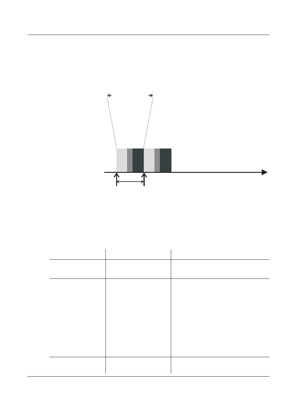
Measuring cycle
A measuring cycle consists of the cleaning procedure, the adjustment
time for the measuring system and the determination of the measured
value. The following graphic demonstrates the relevant settings:
Fig. 3-6 Measuring cycle of the UV-VIS sensor
Carrying out settings
Using , switch from the measured value display to the main menu
of the settings. Then navigate to the setting menu (setting table) of the
sensor. The procedure is described in detail in your IQ S
ENSOR
N
ET
system operating manual.
Default values are marked in bold.
Time
Adjustment time
Measurement
Measuring
cycle
Measuring interval
Cleaning
Menu item
Settings
Explanations
Measuring mode
NO3-N
NO3
The measured parameter is displayed
in the selected citation form.
Measuring location
NitraVis 701 IQ TS
:
Activation
Inlet
Outlet
NitraVis 705 IQ TS
:
Outlet
(permanently set)
Measurement location or application of
the sensor.
The possible measurement loca-
tions are displayed depending on the
currently set measuring mode.
The sample matrix on which the cal-
culation of the measured value is
based changes with the location of
the sensor.
Measuring range
-
Display of the measuring range
(see chapter 8 T