Xylem IM226R02 CP-Series Submersible Motors User Manual
Page 7
CP-Series Submersible Motors Installation, Operation and Maintenance Manual
5
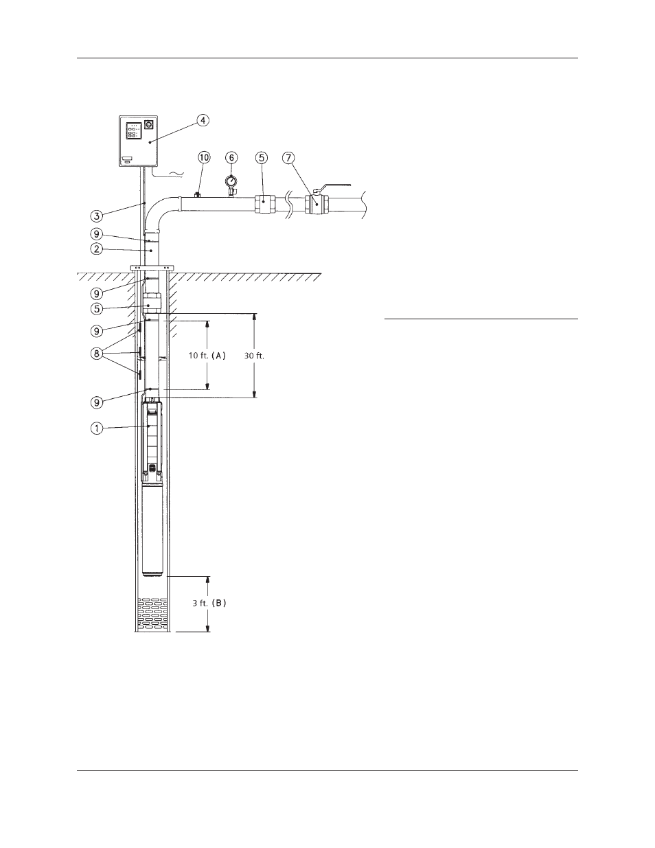
Submersible Pump Installation Diagram
COMPONENTS REQUIRED FOR CORRECT INSTALLATION
• Control panel equipped with a main switch and thermal relay for
overload protection.
• Check valve at 30 feet distance from the delivery ports, plus an
additional non-return valve every 100-165 feet of piping.
• Gauge and gate valve at well mouth.
• Electronic probes or floats for protection against dry running.
RECOMMENDATIONS
• Secure the drop cable to the pipe every 6-10 feet of piping.
• Make sure the motor is installed at a safe distance from the bottom of
the well.
• Make sure there is a minimum distance of .13 inches between the
diameter of the pump and the internal diameter of the well.
• During operation, make sure that the water circulation speed around the
motor is per Section VI #1.
• Make sure that the minimum dynamic level of the water in the well is at
least 3 feet above the pump’s delivery port.
1 - Submersible pump
2 - Delivery pipe
3 - Drop cable
4 - Control panel
5 - Check valve
6 - Gauge
7 - Gate valve
8 - Level sensors for protection against dry
running.
9 - Cable clamp
10 - Pump bleed/priming cap
A - Distance between the clamps that secure
the drop cable to the delivery pipe.
B - Distance from the bottom of the well to
the electric motor.
Submersible Pump Installation Diagram