0 changing a parameter value – Bell & Gossett S13213A MiniBooster Pumping Package User Manual
Page 8
8
APPENDIX 1 - PROGRAMMABLE PUMP
SEQUENCE CONTROL MODULE
1.1
The control system allows for intelligent pump control
while improving system reliability. Timers and relays
used in a conventional controller are integrated into a
single sequence controller. Because all of the timers
and relays are software, changes can be made to the
system operation without costly re-wiring. The work-
ing program is stored on a non-volatile EEPROM chip
that is an integral part of the unit. This means there is
no danger of ever losing a program due to power
losses.
1.2
A 7-day military time clock is standard. It is main-
tained by a super capacitor for a minimum of 8 hours
under a power loss condition. See section 2.4 for
instructions on how to set the clock.
1.3
The following page demonstrates a typical parameter
change. The programming of the module is very simi-
lar to setting a digital watch. As each unit will contain
a program that has been specifically designed for the
application, the actual data you will see will vary from
that shown in the example.
2.0 CHANGING A PARAMETER VALUE
2.1
Adjustable Settings
2.2
If any alarms are shown on the display of the pro-
grammable pump sequence control unit press the
ESC key to proceed with the following instructions.
2.3
Pressing the ESC key will cause the unit display to
show the following selections:
STOP – Do not use, this will stop the program
SET PARAM – Follow instructions as follows
SET CLOCK – Follow instructions as follows
PRG NAME – The name of the program loaded in the
module, such as: 2 pump with duty
Use the up and down arrow keys to select SET PARAM
and press the OK key to accept your selection.
2.4
If you wanted to set the time you would have selected
Set Clock instead. The time would have been set the
same as any other value in the module.
2.5
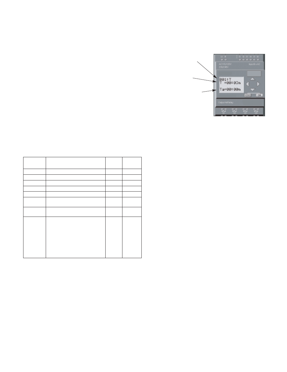
After selecting SET PARAM and pressing the OK key
the display will change as shown to the right.
The parameter number
is indicated here.
The preset value is
indicated here.
A live display of the
timer in question is
shown here. This can be
helpful if you just need
to see when a timer is
about to expire.
2.6
Press the Up and down arrow keys to select the
parameter you wish to change.
2.7
Press OK to edit the displayed parameter.
2.8
Press the left and right arrow keys to select the digit
you wish to change. Selected digit will flash.
2.9
Press the up and down arrow keys to change the
value of the selected digit as required.
2.10 Press OK to accept the change. Pressing the ESC
key instead of OK will abort and the changes will not
be saved.
2.11 Use the ESC key to return to the main screen. Each
time you press the ESC key you will back up one
level from where you are until you finally return to the
normal operating screen, which is the date and time
display.
Parameter
Default Variable
Number
Description
Setting
Range
B01
Lead Pump Minimum Run Timer
10 m
0-99 m
B02
Lag Pump Miimum Run Timer
10 m
0-99 m
B04
Lead Pump Start Delay Timer
1 s
0-99 s
B05
Lag Pump Start Delay Timer
5 s
0-99 s
B07
Pump Fail to Start Delay Timer
5 s
0-99 s
B12
Low Suction/Temp Pump
Shutdown Off-Delay Timer
5 s
0-99 s
B33
Low Suction/Temp Pump
Shutdown On-Delay Timer
5 s
0-99 s
B36
Duty Cycle Alternation
Enable/Disable Switch
OFF
OFF/ON
When setting item B36 the OFF
selection allows the lag pump to
stage on during periods of high
demand. When B36 is set to ON
the lag pump is a standby pump
which will turn on in the event the
lead pump fails.