Bell & gossett, Instructions for pump repair, Periodic inspection – Bell & Gossett P15776H Little Red Booster Pumps User Manual
Page 4
Bell & Gossett
© COPYRIGHT 1982, 2004 BY ITT INDUSTRIES, INC.
PRINTED IN U.S.A. 1-04
USA
Bell & Gossett
8200 N. Austin Avenue
Morton Grove, IL 60053
Phone: (847) 966-3700
Facsimile: (847) 966-9052
http://www.bellgossett.com
INTL.
Bell & Gossett / Export Dept.
8200 N. Austin Avenue
Morton Grove, IL 60053
Phone: (847) 966-3700
Facsimile: (847) 966-8366
http://www.bellgossett.com
CANADA
Fluid Products Canada
55 Royal Road
Guelph, Ontario,
N1H 1T1, Canada
Phone: (519) 821-1900
INSTRUCTIONS FOR PUMP REPAIR
1. Follow steps 1 through 4 of section titled “REMOVAL OF
PUMP FROM EXISTING SYSTEM FOR REPLACEMENT.”
2. Loosen the four capscrews that hold the motor housing to
the pump body. Remove these screws and remove the
housing from the pump body.
3. Place the pump on a flat work surface and insert the plastic
assembly tool (furnished with the repair kit) into the rear
motor housing coverplate middle horizontal vent holes.
Push forward until it engages the rotor cooling fins. This will
lock the rotor allowing removal of the impeller.
4. Remove the impeller nut – left hand thread! – from the pump
shaft. Remove the impeller and rotating seal assembly.
5. Clean the ceramic seat with a clean rag and inspect for
grooving or cracks. If it shows no grooving or cracks, it
may be cleaned and reused.
6. If the ceramic is to be replaced, the face plate must be re-
moved from the motor housing. Remove it by gently pry-
ing it away from the motor housing.
7. Remove the damaged ceramic seat and boot if necessary.
Reinstall new parts in the face plate recess and reposition
the face plate on the motor housing. Gently tap the face
plate evenly around its diameter driving it into the recess
provided in the motor housing.
INSTRUCTIONS FOR PUMP REPAIR
8. Press the rotor fully forward with the plastic assembly
tool. Clean the shaft and sleeve before installing the seal.
9. Press the replacement carbon seal assembly firmly into
the recess in the back side of the impeller.
10. Assemble the seal/impeller assembly to the pump shaft
by pushing the rotor fully forward with the plastic assem-
bly tool. Then slide the seal/impeller assembly onto the
pump shaft until the seal face contacts the ceramic seat.
11. Continue holding the rotor fully forward with the assembly
tool. Install and torque the impeller nut – left hand thread!
– to 15 in-lb (0.17 Kg-m) torque.
12. Clean the recess in the pump body and install a new body
gasket.
13. Install the pump in the body and secure with four cap-
screws. Apply torque evenly in a criss cross pattern to 40
in-lb (0.46 Kg-m) increments to a torque of 80 in-lb (0.92
Kg-m).
14. Reinstall into the system using new flange gaskets. For
instructions, see sections “PUMP INSTALLATIONS”
through and including “LUBRICATION.”
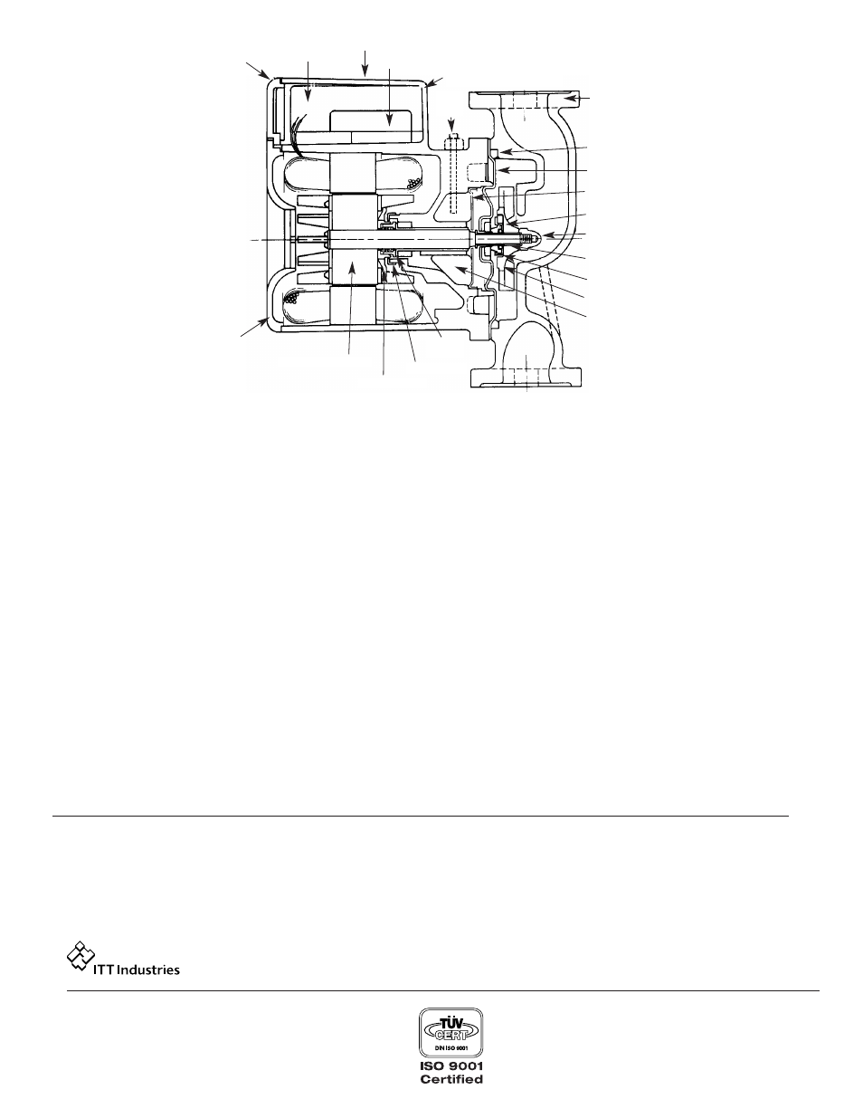
CONDUIT BOX
COVER
CAPACITOR
NAME PLATE
CAPACITOR RETAINER
STATOR & HSG. ASM.
OIL
HOLE
PLUG
BODY
BODY GASKET
COVERPLATE ASM
WICK COVERPLATE
IMP. CUSHION
IMP. NUT
SHAFT SLEEVE
SEAL ASM
IMPELLER
PERMAWICK
THRUST
COLLAR
OIL RETAINER
THRUST DRIVER
MOTOR HSG. COVER
FIG. 6
ROTOR & SHAFT ASM.
PERIODIC INSPECTION
Bell & Gossett Booster Pumps are designed to provide years of
trouble free service. It is recommended that periodic inspec-
tions be made to check for potential problems with the pump. If
PERIODIC INSPECTION
any leakage or evidence of leakage is present repair or replace
the unit.