Pump installation, Typical installation schematic – Bell & Gossett P15776H Little Red Booster Pumps User Manual
Page 3
3
PUMP INSTALLATION
Locate the pump so there is sufficient room for inspection, main-
tenance and service. Bell & Gossett recommends the installa-
tion of service valves on the suction and discharge of all circu-
lators to facilitate servicing or replacement of the circulator
without draining the system.
Install suction and discharge flanges on the pipe ends. The
use of Teflon
®
* tape sealer or a high quality thread sealant is
recommended.
Be sure to minimize any pipe-strain on the pump. Support the
suction and discharge piping by the use of pipe hangers near
the pump. Line up the vertical and horizontal piping so that the
bolt-holes in the pipe flanges match the bolt-holes in the pipe
flanges. [DO NOT ATTEMPT TO SPRING THE SUCTION OR
DISCHARGE LINES IN POSITION. THIS MAY RESULT IN
UNWANTED STRESS IN THE PUMP BODY, FLANGE CON-
NECTIONS AND PIPING.] The code for Pressure Piping
(ANSI B31.1) lists many types of support available for various
applications.
Bell & Gossett flange gaskets must be installed between the
Little Red pump body flanges and the suction and discharge
pipe flanges. Suitable fasteners for this connection are also
supplied in the Bell & Gossett fastener pack.
Apply torque in even increments to both flange bolts until a
value of 175 in-lbs (2.01 Kg-m) is reached. Both the suction
and discharge flanges must be torqued in this manner.
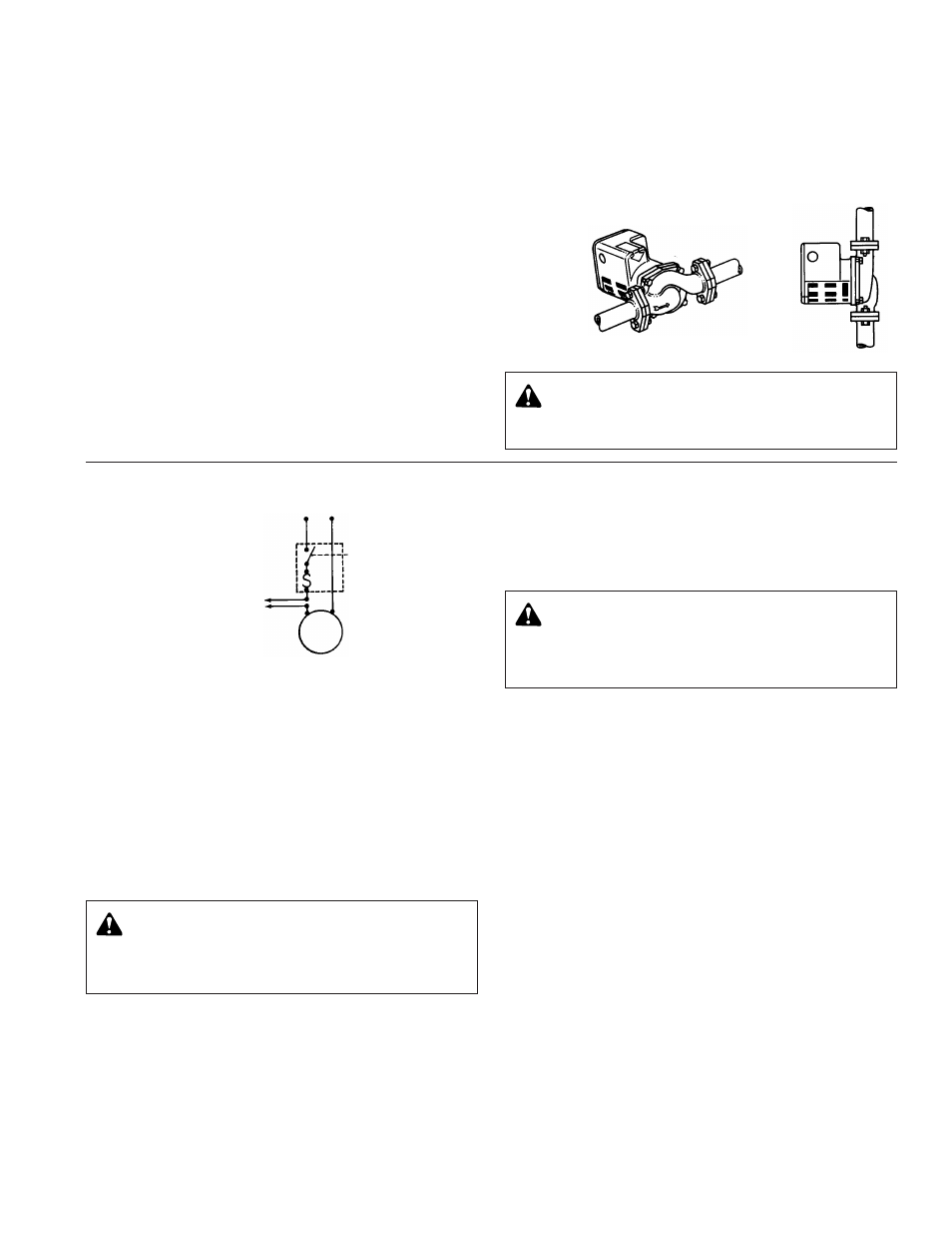
MODE OF DISCHARGE
The Little Red Booster Pump can be installed to discharge up
or down, horizontally left or right, but the oiling port must
always be in the twelve o’clock position (on top). Arrow on
body must point in direction of flow.
TYPICAL INSTALLATION SCHEMATIC
POWER SOURCE 115 Volt. 60 Hz.1ø
ELECTRICAL WIRING
A. Loosen screws securing the conduit box (wiring compart-
ment) cover, removing screws and cover.
B. Select one of the two holes in the side of the conduit box
and wire the motor to a 115 volt, 60 hertz, single phase
power source with number 14 AWG copper electrical wire.
Refer to your local code for wiring restrictions. Plug the
unused hole in the side of the conduit box with the plug
provided.
C. Connect the ground wire to the inside of the conduit box
with the green screw provided.
NOTE: Supply and grounding wires must be suitable for at
least 90°C (194°F).
ELECTRICAL CHARACTERISTICS
Model LR-20BF is rated at 1/20 HP, 115 volts, 1.1 F.L. amps,
60 HZ, 1ø (single phase), 2900 RPM.
Model LR-15B is rated at 1/12 HP, 115 volts, 1.75 F.L. amps,
60 HZ, 1ø (single phase), 3150 RPM.
Little Red Booster Pumps are protected with an inherent over-
heating device and do not require external overload protection.
SYSTEM PREPARATION
Prior to pump start up, closed heating and cooling systems
should be cleaned, drained, and refilled with clean water.
System ph must be maintained between 7 and 9.
Pressurize the pump body slowly while checking for leaks at
all gasketed joints.
PRIMING
Do not run the pump dry. These pumps must be filled with
liquid before being placed in service. Air should be vented
from the system by means of an air vent located at a high
point in the system.
LUBRICATION
All new Bell & Gossett Little Red Booster Pumps are thoroughly
tested at the factory and have been enhanced with a superior
lubrication system which requires a minimum of attention. Please
refer to the recommended lubrication instructions noted below
for the type of pump service required.
1. At installation: Pumps have been factory lubricated and do
not require additional lubrication at start-up.
2. Heating system operation: Pumps should be lubricated at
the start of every heating season. Add one tube (5cc) of
Bell & Gossett P15775 lubricating oil.
3. Continuous duty: Pump should be lubricated every six (6)
months. Add one tube (5cc) of Bell & Gossett P15775 lubri-
cating oil.
NOTE: In lieu of genuine Bell & Gossett P15775 lubricating
oil, use one teaspoon of Mobile 1, SAE 5W-30, motor oil as
required.
IMPORTANT: Over oiling of the pump will result in the
overflow of oil from the oil reservoir.
WARNING: Electrical Shock Hazard
Disconnect and lockout the power before servicing.
Failure to follow these instructions could result in serious
personal injury or death.
WARNING: Electrical Shock Hazard
Be certain that all connections are secure and the
conduit box cover is closed before electrical power is con-
nected. Failure to follow these instructions could result in
serious personal injury or death.
FIG. 4
RIGHT OR
LEFT
UP OR
DOWN
FIG. 5
PUMP
MOTOR
FUSIBLE DISCONNECT
OR CIRCUIT BREAKER
BY OTHERS
PUMP MOTOR
INHERENTLY
PROTECTED
TO REMOTE
CONTROL
IF REQUIRED
WARNING: Hot Water Leakage Hazard
Pressurize the pump body slowly while checking for
leaks at all joints with gaskets. Failure to follow these
instructions could result in serious personal injury and/or
property damage.
*Teflon
®
is a registered trademark of E.I. DuPont de Nemours and Company.