Bell & Gossett DN0154D HS Vented Condensate Units Series HSTM User Manual
Page 6
PUMP SER
VICE INSTRUCTIONS FOR CENTRIFUGAL PUMPS (EXCEPT WATCHMAN
®
/609)
Vertical mounting puts motor above floor dirt and water
Close coupled centrifugal pumps ar
e designed for years of
trouble free service. Units have mechanical shaft seals.
1. Close inlet gate valve and operate pump momentarily to
remove as much liquid as possible from pump. Close dis-
charge line gate valve.
2. Shut-off and lock out power.
3. Make sure unit is cool enough that pump can be handled
safely. Open drain to remove remaining liquid.
4. Carefully remove pump drain plug and bleed line. Wait for
complete drainage.
5. Loosen the motor bracket to pump volute capscrews.
Assure that the pressure is relieved per caution note.
6. Complete the removal of the hardware. Remove pump/
motor assembly and place on work bench.
7. Remove self locking stainless steel capscrews and stain-
less steel washer (or self locking brass cap nut and washer)
that secure the impeller in place.
8. To remove impeller from motor shaft proceed as follows:
(1) Keyed Shafts. Remove impeller with gear puller or other
means which will not damage impeller or bend motor
shaft.
(2) Threaded Shafts. Hold end of motor shaft opposite
pump with large screwdriver or other suitable tool and
back impeller off with a rectangular bar or other flat tool
inserted between the vanes of the impeller.
9. Remove rotating part of seal from shaft, being careful not
break carbon face.
10. Remove capscrews holding motor bracket to motor and
remove bracket.
11. Remove stationary part of seal assembly, being careful not
to chip or break ceramic seal.
12. To install seal proceed as follows:
(1) Clean recess in bracket thoroughly. Coat recess and
“rubber” portion of seat with soap solution. Press seat
into recess firmly by hand making certain both parts bot-
tom evenly. If seal cannot be bottomed with fingers
place cardboard shipping disc on ceramic and force into
place with flat tool.
(2) Carefully place bracket in position on motor shaft with-
out displacing ceramic seat and secure bracket to motor
with capscrews.
(3) Place motor vertically with pump end up. Do not attempt
assembly of seal and impeller with shaft horizontal.
(4) The “carbon” of rotating part of seal should not be loose.
If it is, hold in place with grease. Using clean, lint free
cloth, wipe mating surfaces perfectly clean. Soap shaft
and push seal onto shaft so that carbon will contact
ceramic seal. If spacer is required, use grease to cause
spacer to adhere to bottom of seal after seal has been
put on shaft. Be sure spacer is on larger diameter of
shaft so that will not catch between shoulder and
impeller.
13. Replace impeller on shaft. Replace stainless steel washer
and secure impeller with capscrew or cap nut.
14. Place new gasket on pump volute and reassemble motor
and pump subassembly on pump volute.
15. Reconnect pump bleed line and motor wiring.
16. Close drain and slowly open inlet valves. See warning.
17. Jog to check motor rotation. See caution.
18. Observe operation thru several cycles.
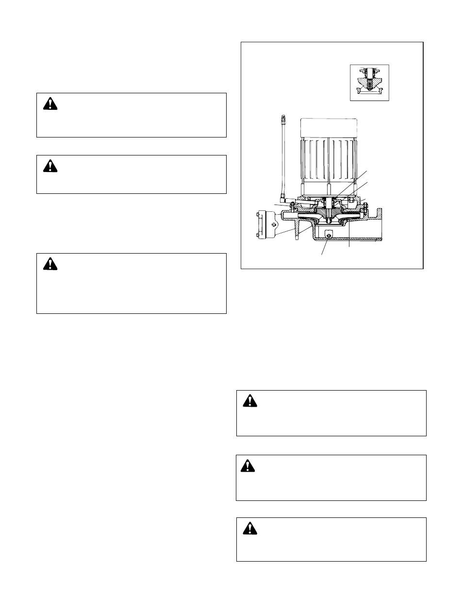
SLINGER
VIEW OF THREADED IMPELLER
WEAR
RING
IMPELLER
2DPF03
VOLUTE
MOTOR
BRACKET
SEAL
CUT-AWAY VIEW OF MECHANICAL
SEAL TYPE PUMP
CAUTION: PRESSURIZED SYSTEM
Operating system may contain very hot water under
pressure. Close inlet and open drains before servicing.
When servicing,
loosen scr
ews and move components to
assure pressure is relieved before
r
emoving
scr
ews. Keep
drains open during servicing. Failure to follow these
instructions could result in injury or property damage.
W
ARNING: HIGH VOLTAGE
Disconnect and lock out power befor
e connecting or
servicing unit. Failure to follow these instructions could
result in serious injury or death.
CAUTION: HOT SURF
ACES
Surfaces ar
e hot when system is in operation. Do not
touch hot receiver, let unit cool before servicing. Failure to
follow these instructions could result in serious injury or
death.
W
ARNING: EXPLOSIBLE
Do not pr
essurize receiver. Isolate receiver during leak
test. Do not plug overflow. Do not restrict vent opening to
atmosphere. Open valves slowly. Failure to follow these
instructions could result in serious injury or death.
CAUTION: DO NOT RUN DR
Y.
SEAL DAMAGE MAY OCCUR.
Inspect pump seal r
egularly for leaks. Replace as
required. Failure to follow these instructions could result in
injury or property damage.
CAUTION: DO NOT REVERSE
Reverse operation can cause extensive damage to
pumps. Jog the motor to test for direction of rotation.
Failure to follow these instructions could result in injury or
property damage.
6