X 16 at least 1 – Bell & Gossett DN0147D HS Underground Condensate and Boiler Feed Units Series UHM User Manual
Page 6
6
PUMP SER
VICE INSTRUCTIONS FOR UNDERGROUND CENTRIFUGAL PUMPS
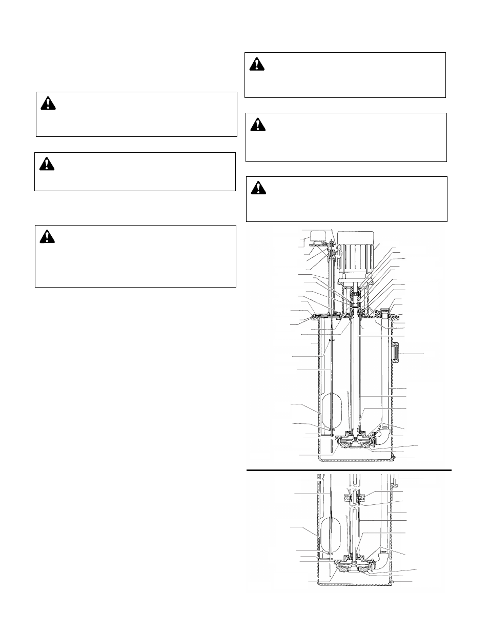
Vertical mounting puts motor above floor dirt and water.
These instructions are for pump disassembly. The mechanical
seal can be replaced without complete pump disassembly as
detailed on the prior page.
1. Close inlet gate valve and operate pump momentarily to
remove as much liquid as possible from pump. Close dis-
charge line gate valve.
2. Shut-off and lock out power.
3. Make sure unit is cool enough that pump can be handled safely.
4. Loosen the discharge pipe. Assure that pressure is relieved
per caution note.
5. Disconnect motor leads, conduit and discharge pipe.
6. Remove coverplate and pump assembly.
7. Remove discharge connection and tubing.
8. Remove capscrews holding volute and lower bearing head.
9. To remove impeller from motor shaft proceed as follows:
a) Remove self locking capnut and washer or self locking cap-
screw and washer.
b) Hold end of shaft opposite pump with suitable tool and
back impeller off with a rectangular bar or other flat tool
inserted between the vanes of the impeller.
10. Remove motor from motor support (half of the flexible cou-
pling will come away with the motor) and set aside.
11. Remove remaining part of flexible coupling. Use puller.
12. Remove grease coverplate from bearing support.
13. Remove the snap-ring from above the bearing.
14. Remove the four capscrews that hold the bearing support.
15. Insert two screws
3
/
8
x 16 at least 1
1
/
2
" long, into the tapped
holes in the flange around the bottom of the bearing support,
and the bearing support by turning both screws evenly, or by
alternating half-turns.
16. With the bearing support freed, remove the stationary part of
the seal, the slinger, and the bearing from the bearing support.
Remove the old gasket.
17. Remove bearing (note: bearing is shielded on lower side).
18. Remove rotating part of seal from shaft. Remove collar when
replacing shaft only.
19. Reassemble pump using new gaskets, reversing procedure
and following mechanical seal replacement steps described
on prior page.
20. When replacing lower bearing, remove lower carbon bearing
from lower bearing head and install new bearing.
Note: If lower bearing is made of bronze, then a complete new
lower bearing head assembly is required.
21. Reconnect pump bleed line and motor wiring.
22. Slowly open inlet gate valve. See warning.
23. Jog to check motor rotation. See caution.
CAUTION:
PRESSURIZED SYSTEM
Operating system may contain very hot water under
pressure. Close inlet and open drains before servicing.
When servicing,
loosen screws and move components to
assure pressure is relieved before
removing screws. Keep
drains open during servicing. Failure to follow these instruc-
tions could result in injury or death.
CAUTION:
HOT SURFACE
Surfaces are hot when system is in operation. Do not
touch hot receiver, let unit cool before servicing. Failure to
follow these instructions could result in serious injury or
death.
WARNING:
HIGH VOLTAGE
Disconnect and lock out power before connecting or
servicing unit. Failure to follow these instructions could
result in serious injury or death.
COLLAR
FLOAT STOP
2DPU02
2DPU04
FLOAT ROD
FLOAT
COLLAR
FLOAT STOP
FLOAT ROD GUIDE
GASKET CASE
IMPELLER
BRONZE ENCLOSED
ORIFICE
ORIFICE
DRAIN PLUG
CASE RING BRASS
CASE
DISCHARGE ELBOW
LOWER BEARING
HEAD
PUMP SUPPORT
COLUMN. PILOTED
DISCHARGE PIPE
INTERMEDIATE
BEARING HOUSING
WHEN USED
INLET
DRAIN PLUG
CASE RING BRASS
CASE
INTERMEDIATE
BEARING OIL-LESS
WHEN USED
LOWER BEARING
OIL-LESS
DISCHARGE ELBOW
LOWER BEARING
HEAD
LOWER BEARING
OIL-LESS
PUMP SUPPORT
COLUMN. PILOTED
DISCHARGE PIPE
INLET
IMPELLER SHAFT
STAINLESS STEEL
SEAL LUBRICATING
ASSEMBLY (WATER)
"O" RING
DISCHARGE FLANGE
EXPANSION JOINT
GASKET
DISCHARGE FLANGE
DISCHARGE FLANGE
GASKET
MOTOR SUPPORT
MOTOR SUPPORT
MECHANICAL SEAL
THRUST BALL BEARING WITH
SINGLE SEAL AND PROVISION
FOR RELUBRICATION
FLEXIBLE COUPLING
CUSHION SPIDER
MOTOR
GREASE CUP
FLOAT SWITCH
AUTOMATIC
ALTERNATOR
DUPLEX UNITS ONLY
SWITCH BRACKET
COLLARS (2)
SWITCH DRIP
VAPOR SEALS (2)
PIPE NIPPLE
RETAINING RING SHAFT
BEARING COVER
BEARING HOUSING
AIR VENT
CONTROL BASE
GASKET
CONTROL BASE
COVER PLATE
GASKET
RECEIVER
SLINGER
STOP COLLAR
MECHANICAL SEAL
RECEIVER CAST IRON
COLLAR
FLOAT STOP
FLOAT ROD
FLOAT
ORIFICE
COLLAR
FLOAT STOP
FLOAT ROD GUIDE
GASKET CASE
IMPELLER
BRONZE ENCLOSED
ORIFICE
KEYS (2)
SET SCREWS (2)
CAUTION:
DO NOT REVERSE
Reverse operation can cause extensive damage to
pumps. Jog the motor to test for direction of rotation.
Failure to follow these instructions could result in serious
injury or death.
CAUTION:
DO NOT RUN DRY.
SEAL DAMAGE MAY OCCUR
Inspect pump seal regularly for leaks Replace as required.
Failure to follow these instructions could result in serious
injury or death.
WARNING:
EXPLOSIBLE
Do not pressurize receiver. Isolate receiver during
leak test. Do not plug overflow. Do not restrict vent opening
to atmosphere. Open valves slowly. Failure to follow these
instructions could result in serious injury or death.