Description, Representative piping diagrams – Bell & Gossett DN0147D HS Underground Condensate and Boiler Feed Units Series UHM User Manual
Page 2
2
DESCRIPTION
Series UH condensate units have one (simplex) or two (duplex)
pumps which are controlled by float(s) switch or mechanical
alternator switch in the receiver.
These pump return accumulated condensate to the boiler feed
system.
Series UHM boiler feed units have one (simplex) or two
(duplex) pumps which are controlled by boiler system con-
trollers. Series UHM receivers are sized to provide for accu-
mulating system surges of condensate. Water makeup valves
are also included to insure that water is always available to
meet boiler demands.
Receivers are non-code cast iron.
PRELIMINARY INSPECTION
Assure that there is no shipping damage.
Assure that nameplate ratings agree with job specifications
and actual conditions.
HANDLING
Use care in installing unit.
LOCATION
Place unit for easy access to all parts. Allow adequate space
for servicing. Check ambient conditions.
NOTICE / TEMPERATURE
LIMITS
Motors are designed to operate in 104ºF max. ambient.
Insulate or ventilate as required.
PIPING (General)
Pipe the unit per the Elementary Piping Diagram. Locate and
support piping so as not to load the pump discharge.
PIPING (Returns)
Gravity return lines from the system must be properly pitched
down to unit inlet. Returns must also be trapped to prevent
steam entry into the unit. An inlet basket strainer is recom-
mended.
PIPING (Vent)
Install a vent pipe to atmosphere. Pipe to be size of vent port
on unit. Do not restrict or reduce vent opening or exceed 20
inch vertical height unless an overflow connection is provided.
FLOAT SWITCHES AND MECHANICAL ALTERNATORS
The floats which operate these switches are factory set but
can be field readjusted as required.
Adjustment is made by removing the float switch as an
assembly and readjusting the stop collars on the float rod.
Setting should utilize as much of the tank volume as practical.
Settings should avoid “short cycling” of the pump. See page 3
for detailed instructions.
ELECTRICAL WIRING & CONTROLS
Connect power wiring per NEC. Recheck nameplate vs. speci
-
fications and conditions. All single phase motors have internal
thermal protection.
Three phase motors must use starters with properly sized
overload relays. Overload relays furnished are designed for
manual reset.
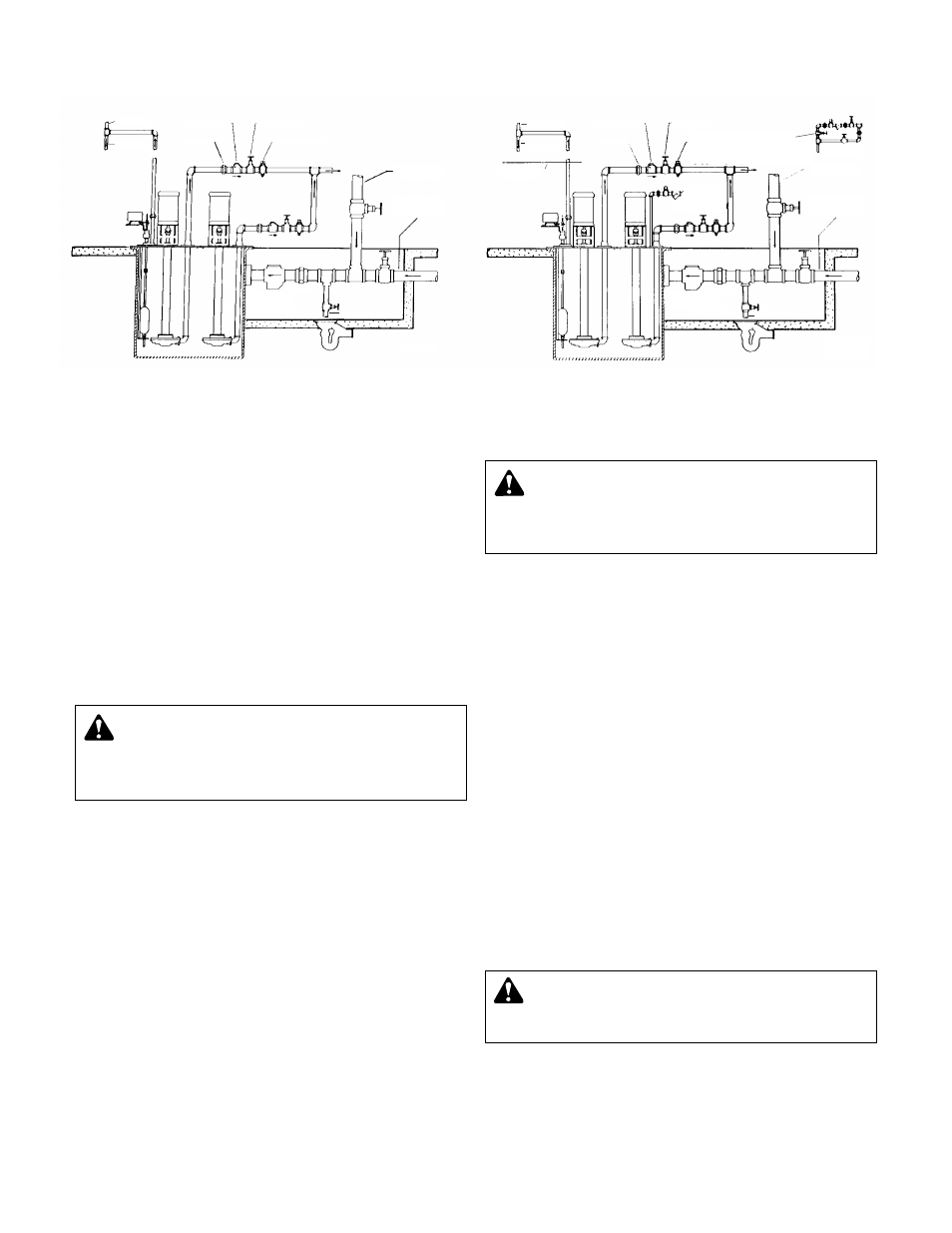
SERIES UH – CONDENSATE UNIT
REPRESENTATIVE PIPING DIAGRAMS
AIR VENT
TO DRAIN
UNION
CHECK VALVE
GATE VALVE
STEAM COCK
DISCHARGE
CONDENSATE
RETURN LINE
UNDERGROUND
CONDENSATE
RETURN LINE
BASKET
STRAINER
(OPTIONAL)
UNION
TO DRAIN
IDPD33
AIR VENT
TO DRAIN
WATER LINE
OF BOILER
UNION
CHECK VALVE
GATE VALVE
STEAM COCK
WATER MAKE-UP
WITH 3 VALVE BYPASS
OPTIONAL
DISCHARGE TO BOILER
DETAIL AA
WATER
MAKE-UP
SUPPLY
(SEE DETAIL AA)
CONDENSATE
RETURN LINE
UNDERGROUND
CONDENSATE
RETURN LINE
BASKET
STRAINER
UNION
TO DRAIN
IDPD44
SERIES UHM BOILER FEED UNIT
WARNING: EXPLOSIBLE
Do not pressurize receiver. Isolate receiver during
leak test. Do not plug overflow. Do not restrict vent opening
to atmosphere. Open valves slowly. Failure to follow these
instructions could result in serious injury or death.
CAUTION:
NOT A CHEMICAL PUMP
Inject boiler feed compounds from chemical feed
tank into boiler feed piping – never into condensate tank.
Failure to follow these instructions could result in injury or
property damage.
WARNING:
HIGH VOLTAGE ELECTRICITY
Disconnect and lock out power before connecting or
servicing unit. Failure to follow these instructions could
result in serious injury or death.