Option b wiring – Bell & Gossett 211013D PSE 800 M Low Water Cut-off User Manual
Page 12
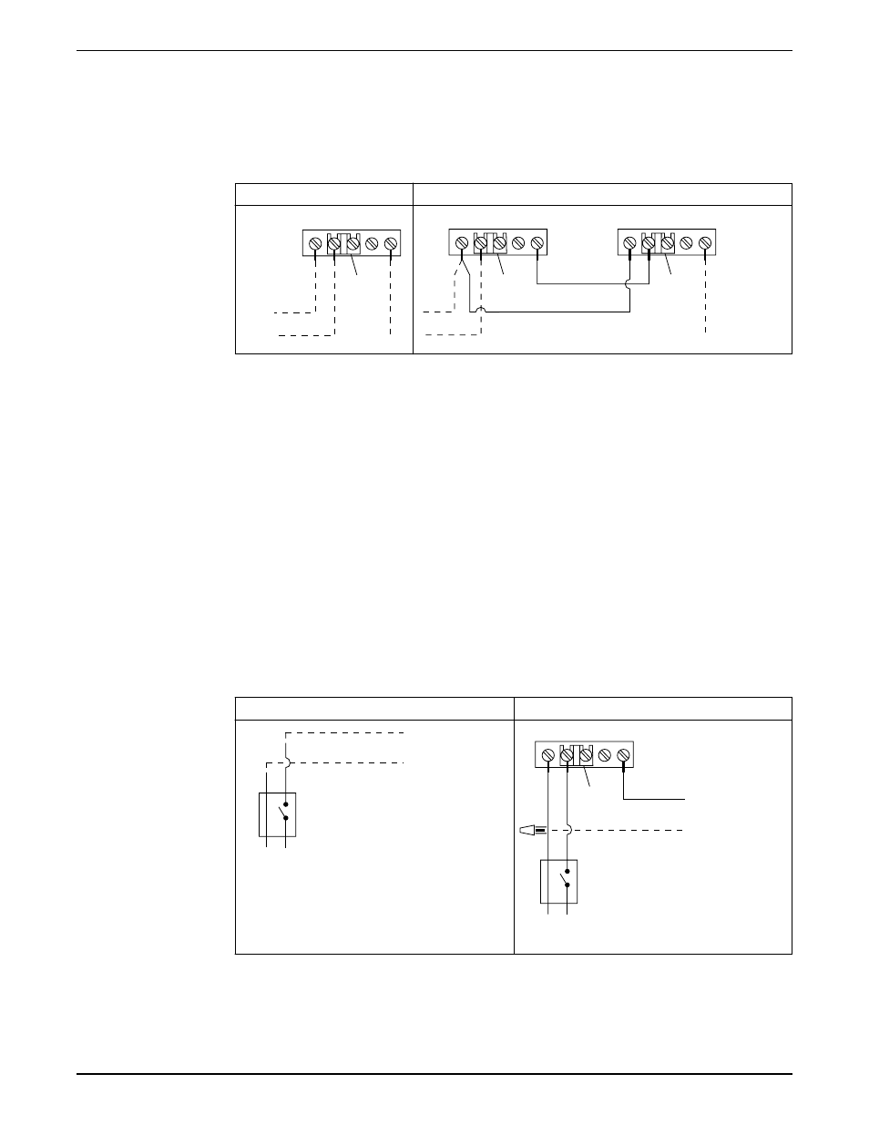
1. Remove existing wire from terminal B of existing Auto Reset LWCO and connect to
terminal B of new Manual Reset LWCO.
2. Connect new wire from terminal B of existing Auto Reset LWCO to terminal H of new
Manual Reset LWCO.
3. Connect new wire from terminal N of existing Auto Reset LWCO to terminal N of new
Manual Reset LWCO.
Existing wiring to boiler
New wiring to boiler
N H C W B
1
N H C W B
1
N H C W B
1
1. Factory jumper bar
_ _ _ _ Dashed lines indicate existing wires.
_____ Solid lines indicate new wires.
Water feeder should be wired to existing Auto Reset LWCO. Wiring diagrams for the
water feeder can be found in the water feeder installation instruction manual.
Option B wiring
Wiring a new 120 V manual reset LWCO to a boiler. Burner circuit voltage could be 24 V
or 120 V. Existing LWCO could be either probe or float type.
1. Remove the existing hot “H” wire from the service switch and the L1 connection on the
boiler.
2. Connect a new hot “H” wire from the service switch to terminal H on the LWCO.
3. Connect a new hot “H” wire from terminal “B” on the LWCO to the L1 connection on
the boiler.
4. Connect a new wire to terminal “N” of the LWCO and splice it to the existing neutral
“N” wire.
Existing wiring to boiler
New wiring to boiler
(L1)
(L1)
N H
120 VAC
2
3
N H C W B
1
(L1)
(L1)
N H
120 VAC
2
3
1. Factory jumper bar
2. Boiler connections
3. Service switch
_ _ _ _ Dashed lines indicate existing wires.
Installation
10
PSE-800-M Low Water Cut-off Installation, Operation, and Maintenance Manual