Pam8010, Typical applications circuit, Pin descriptions – Diodes PAM8010 User Manual
Page 2
PAM8010
Document number: DSxxxxx Rev. 1 - 0
2 of 17
www.diodes.com
November 2012
© Diodes Incorporated
PAM8010
A Product Line of
Diodes Incorporated
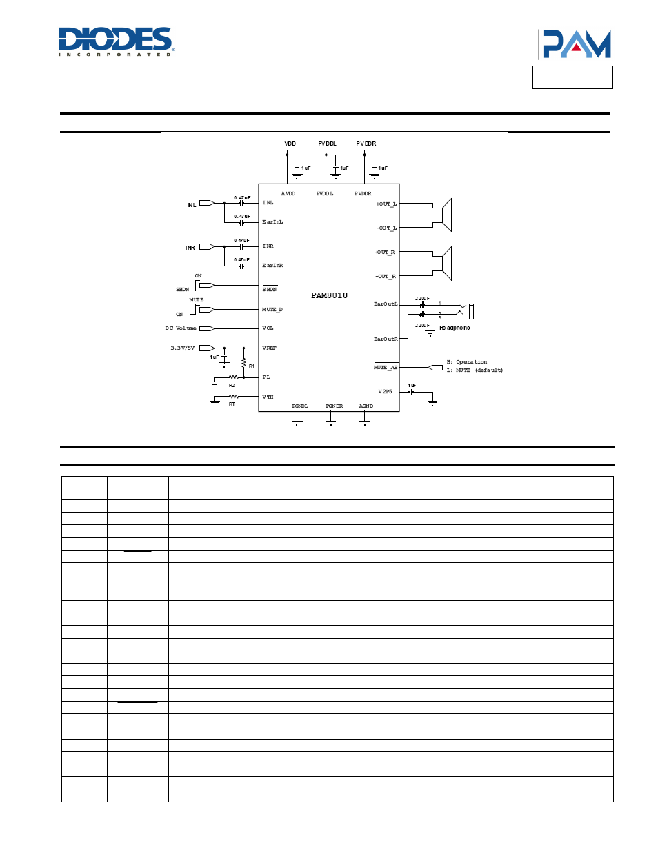
Typical Applications Circuit
Pin Descriptions
Pin
Number
Pin
Name
Function
1
-OUT_L
Left Channel Negative Output
2 PGNDL
Left Channel Power GND
3
+OUT_L
Left Channel Positive Output
4 PVDDL
Left Channel Power Supply
5
SHDN
Full Chip Shutdown Control Input (active low), Pull-Up
6 AVDD
Analog
VDD
7
VREF
Reference Voltage Both for DC Volume Control and Power Limit Section
8
PL
Connect a Resistor Divider from VREF to GND for Power Limit Setting
9
EAR IN L
Left Earphone Input
10
INL
Left Channel Input
11
VOL
Apply DC Voltage at this Pin Set the Gain Both of Class-D and Class-AB
12
EAR OUT L
Left Earphone Output (Non-Inverting)
13
EAR OUT R
Right Earphone Output(Non-Inverting)
14
V2P5
Internal Analog Reference, Connect a Bypass Capacitor from V2P5 to GND
15
IN R
Right Channel Input
16
EAR IN R
Right Earphone Input
17
MUTE_AB
Mute Control of Class-AB Section (active low), Pull-Up
18
VTH
Connect a Resistor from VTH to GND for Noise Threshold Setting
19 AGND
Analog
GND
20
MUTE_D
Mute Control of Class-D Section (active high), Pull-Up
21
PVDDR
Right Channel Power Supply
22
+OUT_R
Right Channel Positive Output
23 PGNDR
Right Channel Power GND
24
-OUT_R
Right Channel Negative Output