Pam2810, Application information – Diodes PAM2810 User Manual
Page 7
PAM2810
Document number: DSxxxxx Rev. 1 - 1
7 of 11
www.diodes.com
October 2012
© Diodes Incorporated
PAM2810
A Product Line of
Diodes Incorporated
Application Information
(cont.)
Shutdown
When the EN pin is logic low, the PAM2810 will be in shutdown mode. While disabled, the PAM2810 typically draws 0.1µA current form the
power supply. There is no internal pull-up or pull-down on the EN pin.
Over Temperature Protection
The PAM2810 equips over temperature protection. When the junction temperature (T
J
) exceeds +150°C, the current source turns off
automatically. The device will turn on again after the IC’s T
J
cools down under +125°C. Operating at absolute maximum temperature is not
recommended.
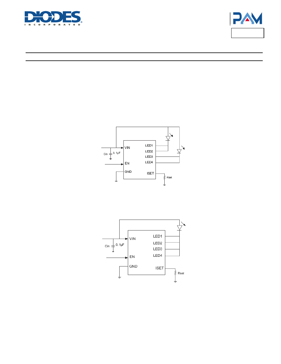
Parallel LEDx Outputs for Increased Current Drive
Output pins LED1 to LED4 may be connected together in any combination to sink higher current through fewer LEDs. For example in Figure 1,
outputs LED1 and LED2 are connected together to drive one LED while LED3 and LED4 are connected together to drive a second LED.
Figure 1. Two Parallel Conneted LEDs
With this configuration, two parallel current sinks of equal value both provide current to each LED. If the current sink provides 10mA each, every
LED can be drived with 20mA and gets double brightness. Other combinations of parallel outputs can be implemented similarly, such as in
Figure 2.
Figure 2. One Parallel Connected LED
Connecting outputs in parallel does not affect internal operation of the PAM2810 and has no impact on the electrical characteristics.
If less than four LEDs connected, the left pin can be floating or connected to GND, as shown in Typical Application Circuit on Page 2.Connecting
to GND is recommended. The current calculating method is the same as the RSET equation mentioned.