Pam2306d, Absolute maximum ratings, Recommended operating conditions – Diodes PAM2306D User Manual
Page 3: Thermal information, Electrical characteristics
PAM2306D
Document number: DSxxxxx Rev. 1 - 1
3 of 12
www.diodes.com
November 2012
© Diodes Incorporated
PAM2306D
A Product Line of
Diodes Incorporated
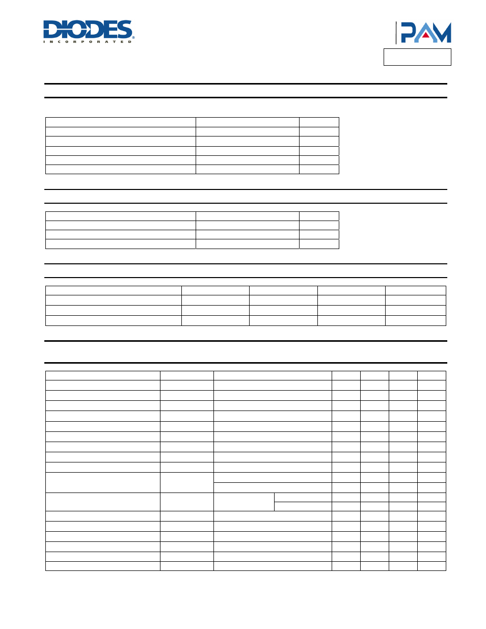
Absolute Maximum Ratings
(@T
A
= +25°C, unless otherwise specified.)
These are stress ratings only and functional operation is not implied. Exposure to absolute maximum ratings for prolonged time periods may affect device
reliability. All voltages are with respect to ground.
Parameter Rating
Unit
Input Voltage
-0.3 to +6.5
V
EN1, FB1, LX1, EN2, FB2 and LX2 Pin Voltage
-0.3 to (V
IN
+0.3)
V
Maximum Junction Temperature
150
°C
Storage Temperature Range
-65 to +150
°C
Soldering Temperature
260, 10sec
°C
Recommended Operating Conditions
(@T
A
= +25°C, unless otherwise specified.)
Parameter Rating
Unit
Supply Voltage
2.5 to 5.5
V
Ambient Temperature Range
-40 to +85
°C
Junction Temperature Range
-40 to +125
°C
Thermal Information
Parameter Symbol
Package
Maximum
Unit
Thermal Resistance (Junction to Ambient)
θ
JA
W-DFN3x3-12
60 °C/W
Thermal Resistance (Junction to Case)
θ
JC
W-DFN3x3-12
8.5 °C/W
Power Dissipation
P
D
W-DFN3x3-12
1.66 W
Electrical Characteristics
(@T
A
= +25°C, V
IN
= 3.6V, V
O
= 1.8V, C
IN
= 10µF, C
O
= 10µF, L = 2.2µH, unless otherwise specified.)
Parameter Symbol
Test
Conditions
Min
Typ
Max
Units
Input Voltage Range
V
IN
2.5
5.5
V
Regulated Feedback Voltage
V
FB
0.588
0.6
0.612
V
Reference Voltage Line Regulation
∆V
FB
0.3
%/V
Regulated Output Voltage Accuracy
V
O
I
O
= 10mA
-3 +3
%
Peak Indictor Current
I
PK
V
IN
= 3V, V
FB
= 0.5V or V
O
= 90%
1.5 A
Output Voltage Line Regulation
LNR
V
IN
= 2.5V to 5V, I
O
= 10mA
0.2
0.5
%/V
Output Voltage Load Regulation
LDR
I
O
= 1mA to 1A
1.5 %
Quiescent Current (per channel)
I
Q
No load
40
70
µA
Shutdown Current (per channel)
I
SD
V
EN
= 0V
0.1 1 µA
Oscillator Frequency
f
OSC
V
O
= 100%
1.2 1.5 1.8 MHz
V
FB
= 0V or V
O
= 0V
500 kHz
Drain-Source On-State Resistance
R
DS(ON)
I
DS
= 100mA
P MOSFET
0.30
0.45
Ω
N MOSFET
0.35
0.50
Ω
SW Leakage Current (per channel)
I
LSW
±0.01
1
µA
EN Threshold High
V
EH
1.5
V
EN Threshold Low
V
EL
0.3
V
EN Leakage Current
I
EN
±0.01
µA
Over Temperature Protection
OTP
150
°C
OTP Hysteresis
OTH
30
°C