Capacitance v voltage, Zxtp4003z, Electrical characteristics – Diodes ZXTP4003Z User Manual
Page 3: Ty p ic a l ga in ( h, Collector current (a), V ) -i, Ca pa c it a nce (p f ) -voltage(v)
ZXTP4003Z
Datasheet Number: DS35460 Rev. 1 - 2
3 of 5
December 2011
© Diodes Incorporated
A Product Line of
Diodes Incorporated
ZXTP4003Z
Electrical Characteristics
@T
A
= 25°C unless otherwise specified
Characteristic Symbol
Min
Typ
Max
Unit
Test
Condition
Collector-Emitter Breakdown Voltage (Note 7)
BV
CEO
-100 -170 -
V I
C
= -10mA
Collector Cut-off Current
I
CBO
- -
-50
nA
V
CB
= -100V
Emitter Cut-off Current
I
EBO
- -
-50
nA
V
EB
= -7V
Static Forward Current Transfer Ratio (Note 7)
h
FE
60
100
133
112
-
-
-
I
C
= -85mA, V
CE
= -0.15V
I
C
= -150mA, V
CE
= -0.2V
Base-Emitter Turn-On Voltage (Note 7)
V
BE(on)
- -0.71
-0.95 V I
C
= -150mA, V
CE
= -0.2V
Delay Time
t
(d)
- 378 - ns
V
CC
= -80V, I
C
= -150mA,f
-I
B2
= 1.5mA, V
CE(ON)
= -0.2V
Rise Time
t
(r)
- 388 - ns
Storage Time
t
(s)
- 1348 -
ns
Fall Time
t
(f)
- 382 - ns
Storage Time
t
(s)
- 75 - ns
V
CC
= -80V, I
C
= -150mA,
-I
B2
= -1.5mA, V
CE(ON)
= -4V
Fall Time
t
(f)
- 363 - ns
Notes:
7. Measured under pulsed conditions. Pulse width = 300
µs. Duty cycle
≤ 2%
Electrical Characteristics
@T
A
= 25°C unless otherwise specified
100µ
1m
10m
100m
1
0
100
200
300
400
500
100µ
1m
10m
100m
1
0.2
0.4
0.6
0.8
1.0
100m
1
10
100
0
10
20
30
40
50
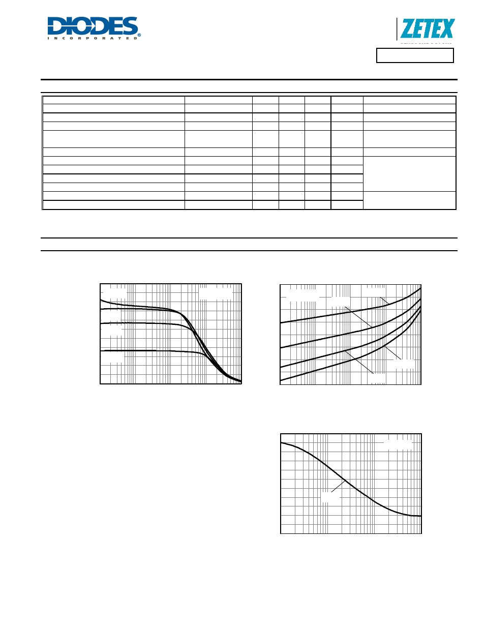
Ty
p
ic
a
l Ga
in
(
h
FE
)
125°C
h
FE
v I
C
V
CE
= -0.2V
-55°C
25°C
85°C
-I
C
Collector Current (A)
125°C
V
BE(on)
v I
C
V
CE
= -0.2V
85°C
25°C
-55°C
-V
BE(
o
n
)
(V
)
-I
C
Collector Current (A)
Capacitance v Voltage
f = 1MHz
Cobo
Ca
pa
c
it
a
nce
(p
F
)
-Voltage(V)