Maximum ratings, Thermal characteristics, Electrical characteristics – Diodes MMBD2004SW User Manual
Page 2: Mmbd2004sw
MMBD2004SW
Document number: DS30443 Rev. 8 - 2
2 of 4
www.diodes.com
August 2013
© Diodes Incorporated
MMBD2004SW
Maximum Ratings
(@T
A
= +25°C, unless otherwise specified.)
Characteristic Symbol
Value
Unit
Repetitive Peak Reverse Voltage
V
RRM
300 V
Working Peak Reverse Voltage
DC Blocking Voltage
V
RWM
V
R
240 V
RMS Reverse Voltage
V
R(RMS)
170 V
Forward Continuous Current
I
F
225 mA
Peak Repetitive Forward Current
I
FRM
625 mA
Non-Repetitive Peak Forward Surge Current
@ t = 1.0µs
@ t = 1.0s
I
FSM
4.0
1.0
A
Thermal Characteristics
Characteristic Symbol
Value
Unit
Power Dissipation (Note 6)
P
D
250 mW
Thermal Resistance Junction to Ambient Air (Note 6)
R
JA
500
C/W
Operating and Storage Temperature Range
T
J
, T
STG
-65 to +150
C
Electrical Characteristics
(@T
A
= +25°C, unless otherwise specified.)
Characteristic Symbol
Min
Max
Unit
Test
Condition
Reverse Breakdown Voltage (Note 7)
V
(BR)R
300
V
I
R
= 100µA
Forward Voltage
V
F
0.87
1.0
V
I
F
= 20mA
I
F
= 100mA
Peak Reverse Current (Note 7)
I
R
100
nA
µA
V
R
= 240V
V
R
= 240V, T
J
= +150
C
Total Capacitance, per Element
C
T
5.0 pF
V
R
= 0, f = 1.0MHz
Reverse Recovery Time
t
rr
50 ns
I
F
= I
R
= 30mA,
I
rr
= 3.0mA, R
L
= 100
Notes:
6. Part mounted on FR-4 PC Board with recommended pad layout, which can be found on our website at http://www.diodes.com.
7. Short duration pulse test used to minimize self-heating effect.
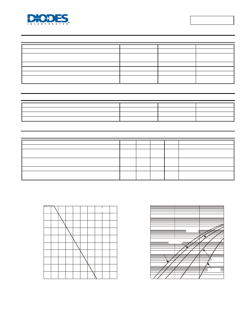
0
50
100
150
200
250
P
, P
O
WE
R
DI
SSI
P
A
T
IO
N (
m
W
)
D
T , AMBIENT TEMPERATURE ( C)
Figure 1 Power Derating Curve, Total Package
A
°
0
40
80
120
160
200
Note 6
I
, INS
TA
N
TA
NEOUS
F
O
R
W
ARD CURRE
NT
(
A
)
F
V , INSTANTANEOUS FORWARD VOLTAGE (V)
Figure 2 Typical Forward Characteristics, Per Element
F
0.00001
0.0001
0.001
0.01
0.1
1
10
0
0.3
0.6
0.9
T = -55°C
J
T = 25°C
J
T = 85°C
J
T = 125°C
J
T =150°C
J