New prod uc t, Maximum ratings, Thermal characteristics – Diodes PD3R1600 User Manual
Page 2: Electrical characteristics
PD3R1600
Document number: DS31654 Rev. 4 - 2
2 of 4
June 2011
© Diodes Incorporated
PD3R1600
POWERDI is a registered trademark of Diodes Incorporated.
NEW PROD
UC
T
Maximum Ratings
@T
A
= 25°C unless otherwise specified
Single phase, half wave, 60Hz, resistive or inductive load.
For capacitance load, derate current by 20%.
Characteristic Symbol
Value
Unit
Peak Repetitive Reverse Voltage
Working Peak Reverse Voltage
DC Blocking Voltage
V
RRM
V
RWM
V
R
600 V
Average Rectified Output Current (see figure 4)
I
O
1.0 A
Non-Repetitive Peak Forward Surge Current
8.3ms Single Half Sine-Wave Superimposed on Rated Load
I
FSM
20 A
Thermal Characteristics
Characteristic Symbol
Typ
Max
Unit
Thermal Resistance, Junction to Ambient Air (Note 3)
R
θJA
125
⎯
°C/W
Operating and Storage Temperature Range
T
J,
T
STG
-65 to +175
°C
Electrical Characteristics
@T
A
= 25°C unless otherwise specified
Characteristic Symbol
Min
Typ
Max
Unit
Test
Condition
Forward Voltage
V
F
⎯
⎯
⎯
0.94
⎯
⎯
⎯
1.1
0.98
V
I
F
= 0.5A
I
F
= 1.0A
I
F
= 1.0A, T
J
= 125°C
Leakage Current (Note 4)
I
R
⎯
⎯
⎯
⎯
1
50
μA
V
R
= 600V
V
R
= 600V, T
J
= 125
°C
Typical Reverse Recovery Time
t
rr
⎯
530
⎯
ns
I
F
= 0.5A, I
R
= 1.0A,
I
rr
= 0.25A
Notes:
3. Polymide PCB, 2 oz. Copper, minimum recommended pad layout peT
A
= 25°C.
4. Short duration pulse test used to minimize self-heating effect.
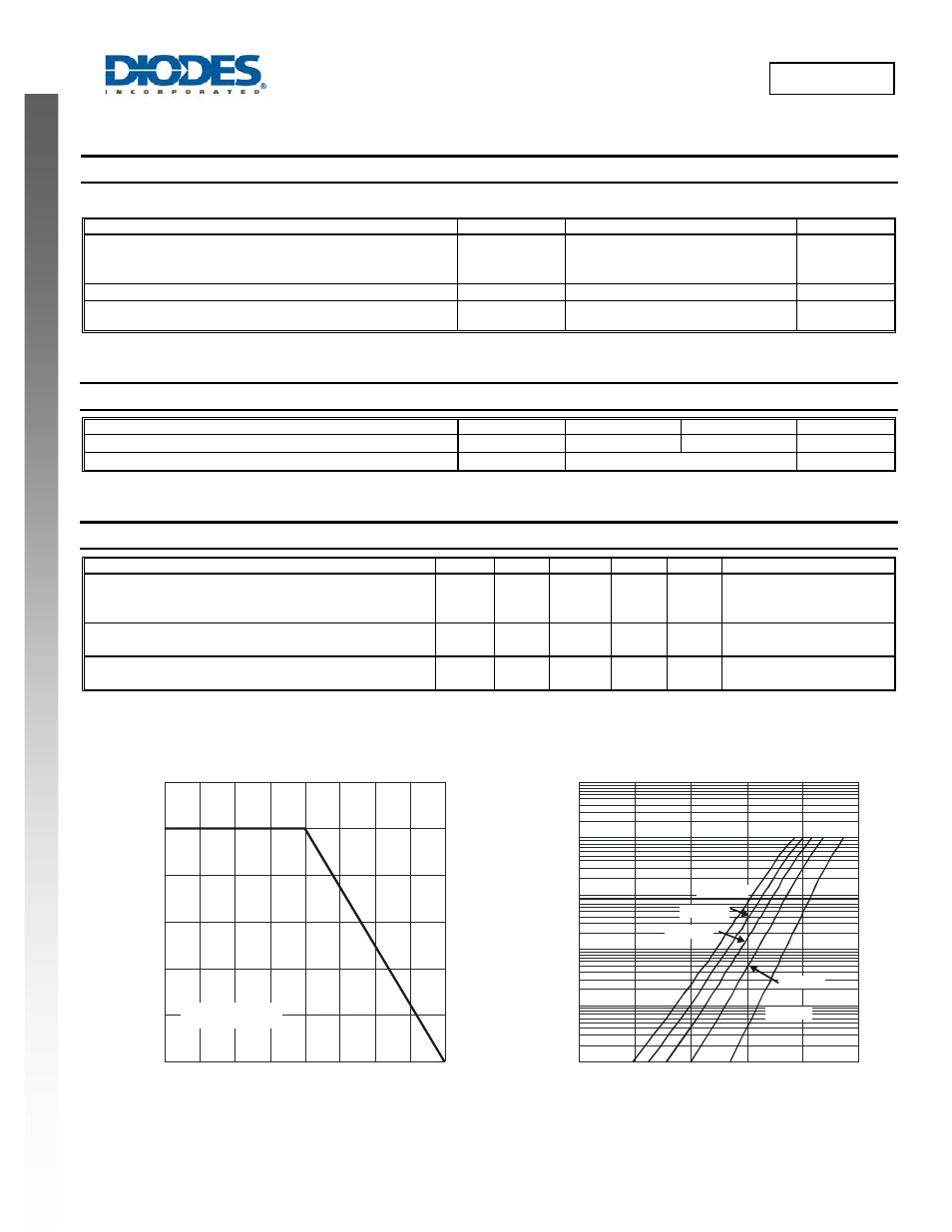
0
0.2
0.4
0.6
0.8
1.0
1.2
95
105
115
125
135
145
155
Fig. 1 Forward Current Derating Curve
T , LEAD TEMPERATURE (°C)
L
I
,
A
VER
AGE F
O
R
W
A
RD CURRE
NT
(
A
)
F(A
V
)
T Measured at the
Cathode Band Terminal
L
165 175
0.1
1
10
100
1,000
10,000
0
0.2
0.4
0.6
0.8
1.0
Fig.2 Typical Forward Characteristics
V , INSTANTANEOUS FORWARD VOLTAGE (V)
F
I
, I
N
ST
ANT
A
NE
OUS F
O
R
W
A
RD CU
RRE
NT
(
m
A)
F
T = 175°C
A
T = 150°C
A
T = 125°C
A
T = 85°C
A
T = 25°C
A