Diodes DDTB (xxxx) U User Manual
Features, Maximum ratings
DS30383 Rev. 6 - 2
1 of 3
www.diodes.com
DDTD (xxxx) U
© Diodes Incorporated
DDTB (xxxx) U
DDTB (xxxx) U
PNP PRE-BIASED 500 mA SURFACE MOUNT TRANSISTOR
Features
•
Epitaxial Planar Die Construction
•
Complementary NPN Types Available (DDTD)
•
Built-In Biasing Resistors, R1, R2
•
Lead Free/RoHS Compliant (Note 2)
•
"Green" Device (Note 3 and 4)
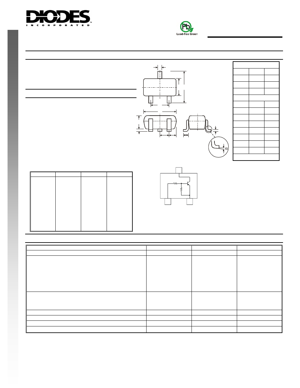
Mechanical Data
N
E
W
ODOD
P P
R
U
C
T
T
R
U
C
•
Case: SOT-323
•
Case Material: Molded Plastic, "Green" Molding
Compound, Note 4. UL Flammability Classification
Rating 94V-0
•
Moisture Sensitivity: Level 1 per J-STD-020C
•
Terminal Connections: See Diagram
•
Terminals: Solderable per MIL-STD-202, Method 208
•
Lead Free Plating (Matte Tin Finish annealed over Alloy
42 leadframe).
•
Marking Code & Date Code Information: See Table
Below & Page 3
•
Ordering Information: See Page 3
•
Weight: 0.006 grams (approximate)
P/N
R1 (NOM)
R2 (NOM)
Type Code
DDTB113EU
DDTB123EU
DDTB143EU
DDTB114EU
DDTB122JU
DDTB113ZU
DDTB123YU
DDTB133HU
DDTB123TU
DDTB143TU
DDTB114TU
DDTB114GU
1K
2.2K
4.7K
10K
0.22K
1K
2.2K
3.3K
2.2K
4.7K
10K
0
1K
2.2K
4.7K
10K
4.7K
10K
10K
10K
OPEN
OPEN
OPEN
10K
P60
P61
P62
P63
P64
P65
P66
P67
P69
P70
P71
P72
SOT-323
Dim
Min
Max
A
0.25
0.40
B
1.15
1.35
C
2.00
2.20
D
0.65 Nominal
E
0.30
0.40
G
1.20
1.40
H
1.80
2.20
J
0.0
0.10
K
0.90
1.00
L
0.25
0.40
M
0.10
0.18
α
0
°
8
°
All Dimensions in mm
A
M
J
L
E
D
C
B
Maximum Ratings
@T
A
= 25°C unless otherwise specified
Characteristic
Symbol
Value
Unit
Supply Voltage, (3) to (2)
V
CC
-50
V
Input Voltage, (1) to (2)
DDTB113EU
DDTB123EU
DDTB143EU
DDTB114EU
DDTB122JU
DDTB113ZU
DDTB123YU
DDTB133HU
V
IN
+10 to -10
+10 to -12
+10 to -30
+10 to -40
+5 to -5
+5 to -10
+5 to -12
+6 to -20
V
Input Voltage, (2) to (1)
DDTB123TU
DDTB143TU
DDTB114TU
DDTB114GU
V
EBO (MAX)
-5
V
Output Current All
I
C
-500
mA
Power Dissipation
P
d
200
mW
Thermal Resistance, Junction to Ambient Air (Note 1)
R
θJA
625
°C/W
Operating and Storage Temperature Range
T
j
, T
STG
-55 to +150
°C
Notes:
1. Mounted on FR4 PC Board with recommended pad layout at http://www.diodes.com/datasheets/ap02001.pdf.
2. No purposefully added lead.
3. Diodes Inc.'s "Green" policy can be found on our website at http://www.diodes.com/products/lead_free/index.php.
4. Product manufactured with Date Code 0627 (week 27, 2006) and newer are built with Green Molding Compound. Product manufactured prior to
Date Code 0627 are built with Non-Green Molding Compound and may contain Halogens or Sb2O3 Fire Retardants.
Schematic and Pin Configuration
H
K
G
R1
OUT
B
C
E
R2
3
2
1
IN
GND(+)