Diodes FCX717 User Manual
Fcx717, Sot89 pnp silicon power (switching) transistor
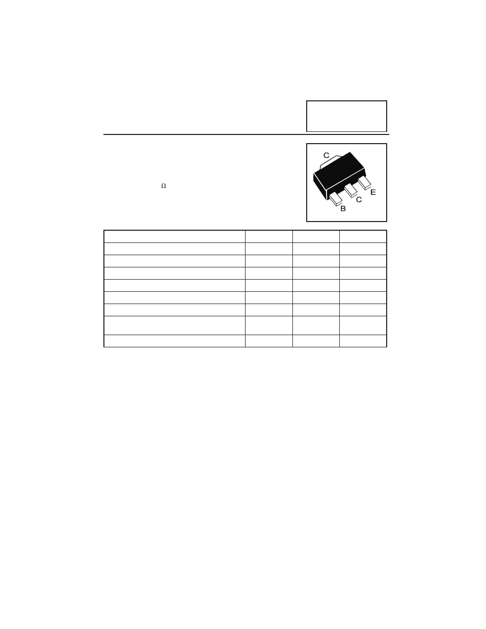
SOT89 PNP SILICON POWER
(SWITCHING) TRANSISTOR
ISSSUE 1 - MAY 1999
FEATURES
*
2W POWER DISSIPATION
*
10A Peak Pulse Current
*
Excellent H
FE
Characteristics up to 10 Amps
*
Extremely Low Saturation Voltage E.g. 12mv Typ.
*
Extremely Low Equivalent On-resistance;
R
CE(sat)
77m
at 3A
Partmarking Detail -
717
ABSOLUTE MAXIMUM RATINGS.
PARAMETER
SYMBOL
VALUE
UNIT
Collector-Base Voltage
V
CBO
-12
V
Collector-Emitter Voltage
V
CEO
-12
V
Emitter-Base Voltage
V
EBO
-5
V
Peak Pulse Current **
I
CM
-10
A
Continuous Collector Current
I
C
-3
A
Base Current
I
B
-500
mA
Power Dissipation at T
amb
=25°C
P
tot
1 †
2 ‡
W
W
Operating and Storage Temperature Range
T
j
:T
stg
-55 to +150
°C
†
recommended P
tot
calculated using FR4 measuring 15x15x0.6mm
‡
Maximum power dissipation is calculated assuming that the device is mounted on FR4
substrate measuring 40x40x0.6mm and using comparable measurement methods adopted by
other suppliers.
**Measured under pulsed conditions. Pulse width=300
µ
s. Duty cycle
2%
Spice parameter data is available upon request for these devices
Refer to the handling instructions for soldering surface mount components.
FCX717