Diodes KBJ4005G - KBJ410G User Manual
0a glass passivated bridge rectifier, Mechanical data, Maximum ratings and electrical characteristics
e
3
DS21206 Rev. 9 - 2
1 of 3
KBJ4005G-KBJ410G
www.diodes.com
ã
Diodes Incorporated
KBJ4005G - KBJ410G
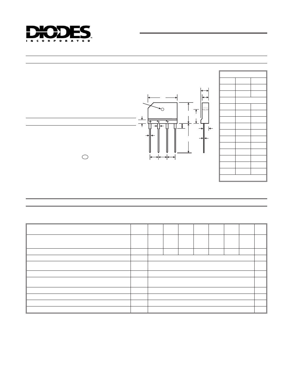
4.0A GLASS PASSIVATED BRIDGE RECTIFIER
·
Case: KBJ
·
Case Material: Molded Plastic. UL Flammability
Classification Rating 94V-0
·
Moisture Sensitivity: Level 1 per J-STD-020C
·
Terminals: Finish - Tin. Plated Leads, Solderable per
MIL-STD-202, Method 208
·
Polarity: Molded on Body
·
Mounting: Through Hole for #6 Screw
·
Mounting Torque: 5.0 in-lbs Maximum
·
Ordering Information: See Last Page
·
Marking: Type Number
·
Weight: 4.6 grams (approximate)
Mechanical Data
·
Glass Passivated Die Construction
·
High Case Dielectric Strength of 1500V
RMS
·
Low Reverse Leakage Current
·
Surge Overload Rating to 120A Peak
·
Ideal for Printed Circuit Board Applications
·
UL Listed Under Recognized Component Index, File
Number E94661
·
Lead Free Finish, RoHS Compliant (Note 4)
Single phase, half wave, 60Hz, resistive or inductive load.
For capacitive load, derate current by 20%.
Maximum Ratings and Electrical Characteristics
@ T
A
= 25°C unless otherwise specified
_
A
B
D
J
K
C
E
G
H
L
M
N
P
R
KBJ
Dim
Min
Max
A
24.80
25.20
B
14.70
15.30
C
4.00 Nominal
D
17.20
17.80
E
0.90
1.10
G
7.30
7.70
H
3.10
Ж 3.40 Ж
J
3.30
3.70
K
1.50
1.90
L
9.30
9.70
M
2.50
2.90
N
3.40
3.80
P
4.40
4.80
R
0.60
0.80
All Dimensions in mm
Characteristic
Symbol
KBJ
4005G
KBJ
401G
KBJ
402G
KBJ
404G
KBJ
406G
KBJ
408G
KBJ
410G
Unit
Peak Repetitive Reverse Voltage
Working Peak Reverse Voltage
DC Blocking Voltage
V
RRM
V
RWM
V
R
50
100
200
400
600
800
1000
V
RMS Reverse Voltage
V
R(RMS)
35
70
140
280
420
560
700
V
Average Rectified Output Current
@ T
C
= 115°C
I
O
4.0
A
Non-Repetitive Peak Forward Surge Current, 8.3 ms single
half-sine-wave superimposed on rated load
I
FSM
120
A
Forward Voltage per element
@ I
F
= 2.0A
V
FM
1.0
V
Peak Reverse Current
@ T
C
= 25°C
at Rated DC Blocking Voltage
@ T
C
= 125°C
I
RM
5.0
500
µA
I
2
t Rating for Fusing, t <8.3ms (Note 3)
I
2
t
60
A
2
s
Typical Total Capacitance per Element (Note 1)
C
T
40
pF
Typical Thermal Resistance (Note 2)
R
qJC
5.5
°C/W
Operating and Storage Temperature Range
T
j
, T
STG
-65 to +150
°C
Notes: 1. Measured at 1.0 MHz and applied reverse voltage of 4.0V DC.
2. Thermal resistance from junction to case per element. Unit mounted on 75 x 75 x 1.6mm aluminum plate heat sink.
3. Non-repetitive, for t
>1ms and <8.3ms.
4. RoHs
Features