Dsr8a600 new prod uc t, Maximum ratings, Thermal characteristics – Diodes DSR8A600 User Manual
Page 2: Electrical characteristics
DSR8A600
Document number: DS36247 Rev. 2 - 2
2 of 6
September 2013
© Diodes Incorporated
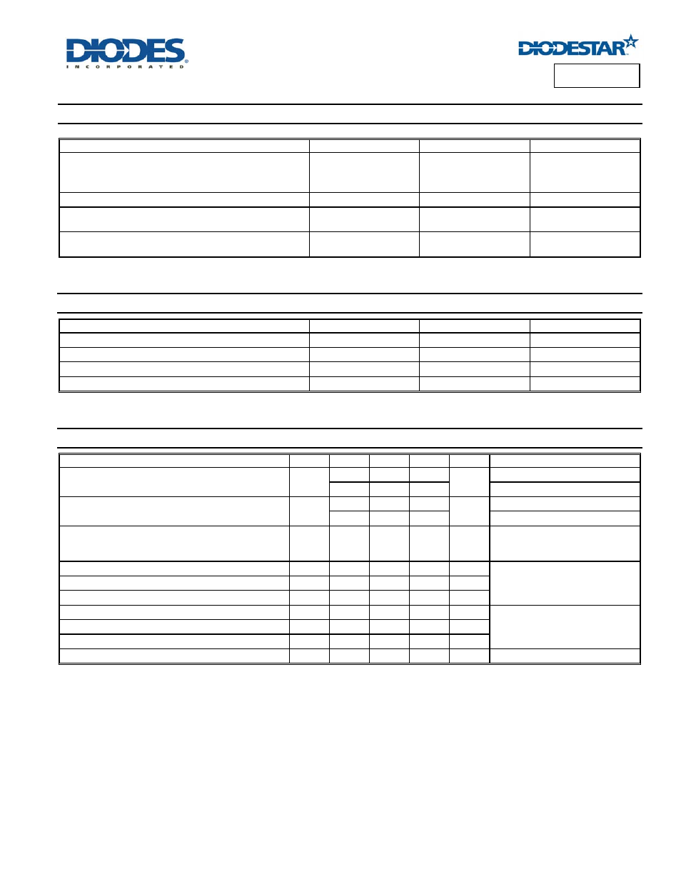
DSR8A600
NEW PROD
UC
T
Maximum Ratings
(@T
A
= +25°C, unless otherwise specified.)
Single phase, half wave, 60Hz, resistive or inductive load.
Characteristic Symbol
Value
Unit
Peak Repetitive Reverse Voltage
Working Peak Reverse Voltage
DC Blocking Voltage
V
RRM
V
RWM
V
RM
600 V
Average Rectified Output Current T
≤ +101°C
I
O
8 A
Non-Repetitive Peak Forward Surge Current 8.3ms
Single Half Sine-Wave Superimposed on Rated Load
I
FSM
65 A
Non-Repetitive Peak Forward Surge Current 10ms
Single Half Sine-Wave Superimposed on Rated Load
I
FSM
60 A
Thermal Characteristics
Characteristic Symbol
Value
Unit
Typical Thermal Resistance, Junction to Lead (Note 4)
R
θJL
2 °C/W
Typical Thermal Resistance, Junction to Ambient (Note 5)
R
θJA
62 °C/W
Storage Temperature Range
T
STG
-55 to +150
°C
Maximum Operating Junction Temperature
T
J
+150 °C
Electrical Characteristics
(@T
A
= +25°C, unless otherwise specified.)
Characteristic Symbol
Min
Typ
Max
Unit
Test
Condition
Forward Voltage Drop
V
F
— 2.3 3.2
V
I
F
= 8A, T
J
= +25°C
— 1.6 —
I
F
= 8A, T
J
= +125°C
Leakage Current (Note 6)
I
R
— <1 20
µA
V
R
= 600V, T
J
= +25°C
— 100 —
V
R
= 600V, T
J
= +125°C
Reverse Recovery Time
t
rr
— 25 30 ns
I
F
= 1A, I
R
= 0.5A, I
RR
= 0.25A , RG1
Reverse Recovery Time
t
rr
— 20 — ns
I
F
= 8A, dl/dt = 500A/µs,
V
R
= 390V, T
J
= +25°C
Reverse Recovery Current
I
RM
— 6.9 — A
Reverse Recovery Charges
Q
rr
— 85 — nC
Reverse Recovery Time
t
rr
— 37 ns
I
F
= 8A, dl/dt = 500A/µs,
V
R
= 390V, T
J
= +125°C
Reverse Recovery Current
I
RM
— 8.3 — A
Reverse Recovery Charges
Q
rr
— 161 — nC
Junction Capacitance
C
J
— 7.7 — pF
100.0V,
1MHz
Notes:
4. Measured from Cathode Tab.
5. Device free standing with no Heat sink.
6. Short duration pulse test used to minimize self-heating effect.