New prod uc t dsrhd02 – dsrhd08, Maximum ratings, Thermal characteristics – Diodes DSRHD02 – DSRHD08 User Manual
Page 2: Electrical characteristics
DSRHD02-DSRHD08
Document number: DS35952 Rev. 4 - 2
2 of 4
November 2012
© Diodes Incorporated
NEW PROD
UC
T
DSRHD02 – DSRHD08
Maximum Ratings
(@T
A
= +25°C, unless otherwise specified.)
Single phase, half wave, 60Hz, resistive or inductive load.
For capacitance load, derate current by 20%.
Characteristic
Symbol DSRHD02 DSRHD04 DSRHD06 DSRHD08 Unit
Peak Repetitive Reverse Voltage
Working Peak Reverse Voltage
DC Blocking Voltage
V
RRM
V
RWM
V
RM
200 400 600 800
V
Average Rectified Output Current
I
O
1.0 A
Non-Repetitive Peak Forward Surge Current 8.3ms
Single Half Sine-Wave Superimposed on Rated Load (Per Diode)
I
FSM
30 A
Minimum Fusing Current Rating (t < 8.3 ms)
I
2
t 3.73
A
2
s
Thermal Characteristics
Characteristic Symbol
Value
Unit
Typical Thermal Resistance Junction to Lead
R
θJL
25 °C/W
Typical Thermal Resistance Junction to Ambient
On Aluminum Substrate
R
θJA
62.5
°C/W
On Glass-Epoxy Substrate
80
Operating and Storage Temperature Range
T
J
, T
STG
-55 to +150
°C
Electrical Characteristics
(@T
A
= +25°C, unless otherwise specified.)
Characteristic Symbol
Max
Unit
Test
Condition
Forward Voltage (Per Diode)
V
F
0.95
V
I
F
= 0.4A, T
J
= +25°C
1.1
I
F
= 1.0A, T
J
= +25°C
Reverse Current (Note 5) (Per Diode) V
R
= Rated Block Voltage
I
R
10
150
μA
V
R
= Rated Block Voltage,
T
J
= 25°C
T
J
= 125°C
Notes:
5. Short duration pulse test used to minimize self-heating effect.
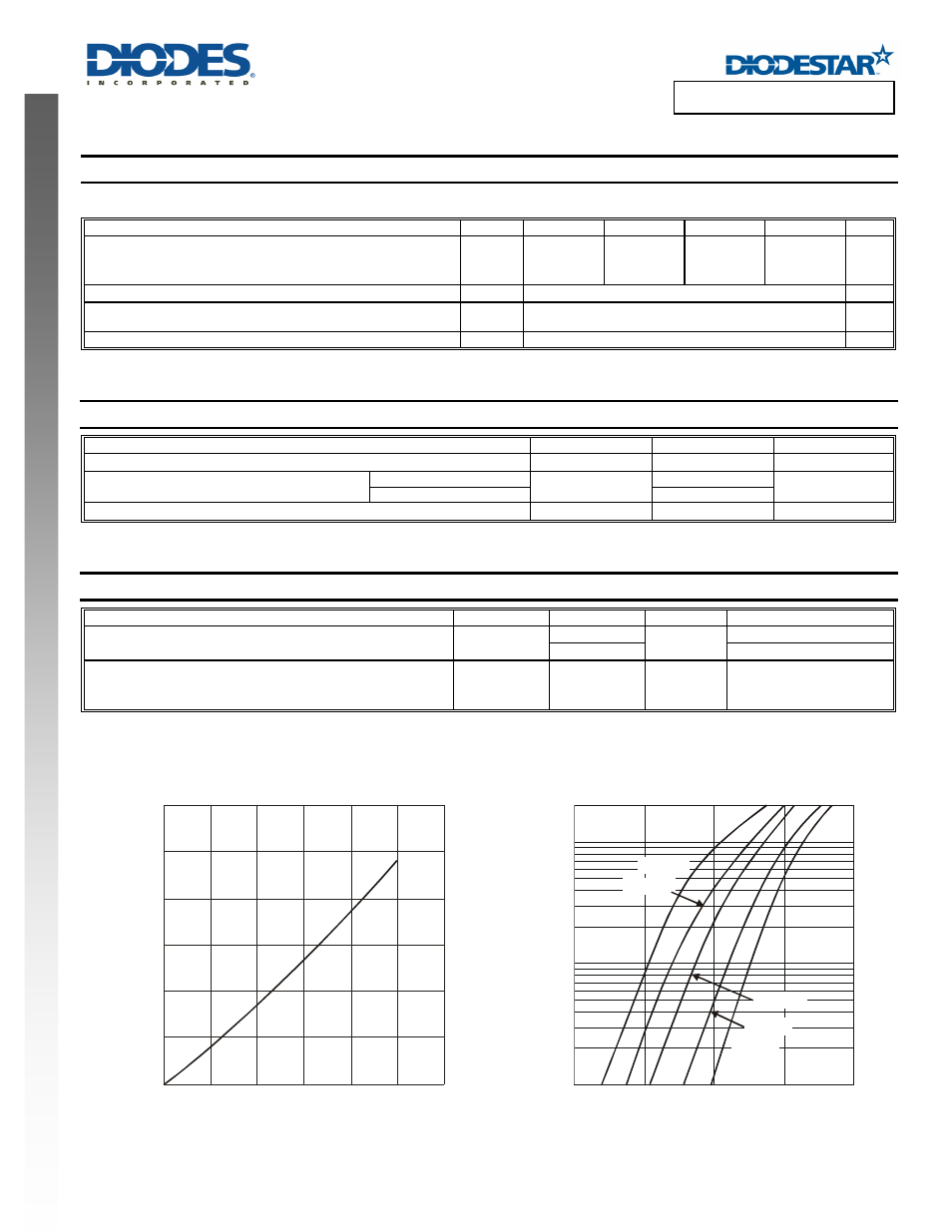
0
0.2
0.4
0.6
0.8
1.0
1.2
P
, P
O
WE
R
D
ISSI
P
A
T
IO
N
(W
)
D
Fig. 1 Forward Power Dissipation
0
0.2
0.4
0.6
0.8
1.0
1.2
I
, AVERAGE FORWARD CURRENT (A)
F(AV)
0.01
0.1
1
0.3
0.5
0.7
0.9
1.1
Fig. 2 Typical Forward Characteristics
V , INSTANTANEOUS FORWARD VOLTAGE (V)
F
I
, I
N
ST
ANT
A
NEOUS
F
O
RW
ARD C
URRENT
(
A
)
F
T = 25°C
A
T = 75°C
A
T = 125°C
A
T = 150°C
A
T = 100°C
A