Maximum ratings (per leg), Thermal characteristics (per leg), Electrical characteristics (per leg) – Diodes MBRF1030CT- MBRF1060CT User Manual
Page 2
MBRF1030CT-MBRF1060CT
Document number: DS35378 Rev. 5 - 2
2 of 4
October 2013
© Diodes Incorporated
MBRF1030CT- MBRF1060CT
Maximum Ratings (Per Leg)
(@T
A
= +25°C, unless otherwise specified.)
Single phase, half wave, 60Hz, resistive or inductive load.
For capacitive load, derate current by 20%.
Characteristic Symbol
MBRF
1030CT
MBRF
1040CT
MBRF
1045CT
MBRF
1050CT
MBRF
1060CT
Unit
Peak Repetitive Reverse Voltage
Working Peak Reverse Voltage
DC Blocking Voltage
V
RRM
V
RWM
V
R
30 40 45 50 60 V
RMS Reverse Voltage
V
R(RMS)
21 28 31.5 35 42 V
Average Rectified Output Current (Note 5)
(Per Leg)
(Total)
I
O
5
10
A
Non-Repetitive Peak Forward Surge Current
8.3ms Single Half Sine-Wave Superimposed on Rated Load
I
FSM
100 A
Thermal Characteristics (Per Leg)
Characteristic Symbol
Value
Unit
Typical Thermal Resistance Junction to Case (Note 5)
R
θJC
5 K/W
Operating and Storage Temperature Range
T
J
,
T
STG
-55 to +150
°C
Electrical Characteristics (Per Leg)
(@T
A
= +25°C, unless otherwise specified.)
Characteristic Symbol
MBRF
1030CT
MBRF
1040CT
MBRF
1045CT
MBRF
1050CT
MBRF
1060CT
Unit
Forward Voltage Drop Maximum @ I
F
= 5.0A, T
C
= +125°C
@ I
F
= 5.0A, T
C
= +25°C
V
FM
0.55
0.65
0.65
0.75
V
Peak Reverse Current Maximum @ T
C
= +25°C
at Rated DC Blocking Voltage (Note 6) @ T
C
= +125°C
I
RM
0.1
15
mA
Typical Total Capacitance (Note 7)
C
T
150 pF
Notes:
5. Device mounted on Device with additional heat sink (45mm X 20mm X 12mm), with minimum recommended pad layout per
6. Short duration pulse test used to minimize self-heating effect.
7. Measured at 1.0 MHz and applied reverse voltage of 4.0V DC and per element.
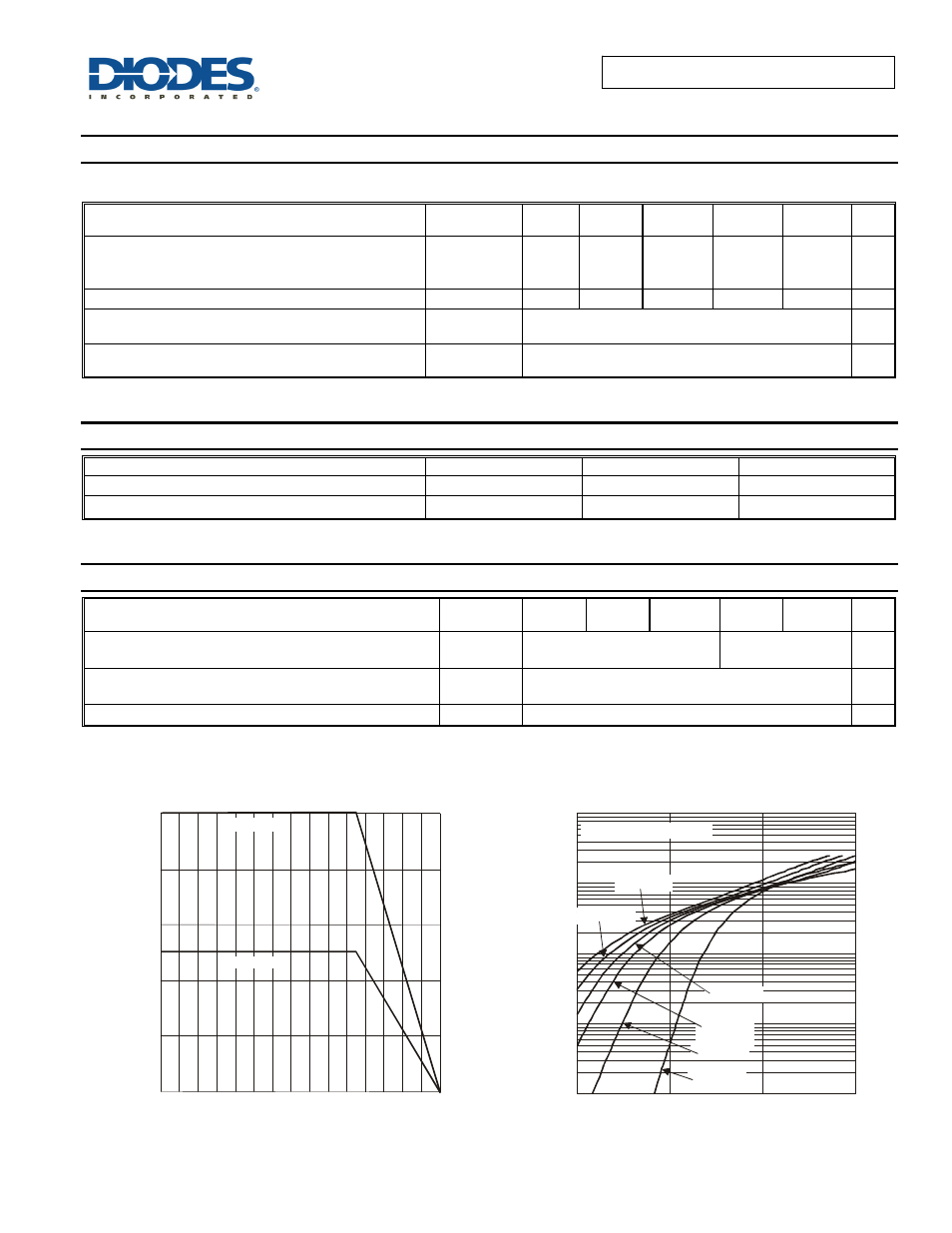
0
2
4
6
8
10
0
50
100
150
I,
A
V
E
R
A
G
E
F
O
R
ZW
A
R
D
C
U
R
R
EN
T
(A
)
(A
V
)
T , CASE TEMPERATURE ( C)
Figure 1 Forward Current Derating Curve
C
°
Total Device
Per Element
I
, INS
TANT
A
NEOUS
F
O
R
W
ARD CURR
ENT
(
A
)
F
V , INSTANTANEOUS FORWARD VOLTAGE (V)
Figure 2 Typical Forward Characteristics, per Element
F
T = -55°C
J
MBRF1030CT - MBRF1045CT
100
0.2
0.4
0.6
0.8
10
0.1
0.01
1
T = 125°C
J
T = 100°C
J
T = 75°C
J
T = 150°C
J
T = 25°C
J