B140hw, Maximum ratings, Thermal characteristics – Diodes B140HW User Manual
Page 2: Electrical characteristics
B140HW
Document number: DS30670 Rev. 9 - 2
2 of 5
May 2012
© Diodes Incorporated
B140HW
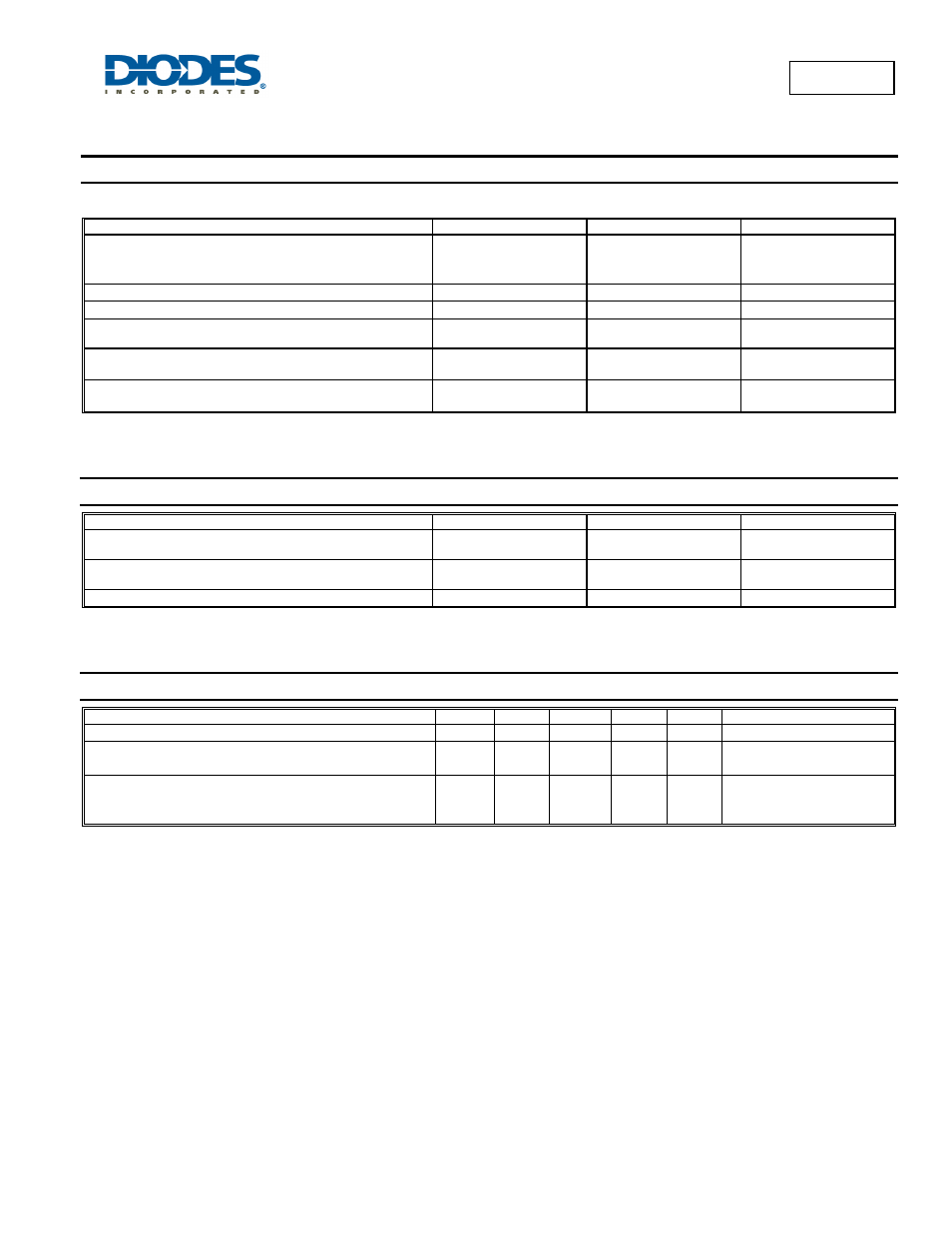
Maximum Ratings
@T
A
= 25°C unless otherwise specified
Single phase, half wave, 60Hz, resistive or inductive load.
For capacitance load, derate current by 20%.
Characteristic Symbol
Value
Unit
Peak Repetitive Reverse Voltage
Working Peak Reverse Voltage
DC Blocking Voltage
V
RRM
V
RWM
V
R
40 V
RMS Reverse Voltage
V
R(RMS)
28 V
Average Forward Current (See Figure 1)
I
F(AV)
1.0 A
Non-Repetitive Peak Forward Surge Current 8.3ms
single half sine-wave superimposed on rated load
I
FSM
16 A
Repetitive Peak Reverse Current
t
p
= 2
μs square wave, f = 1KHz
I
RRM
0.5 A
Non-Repetitive Peak Reverse Current
t
p
= 100
μs square wave
I
RSM
1.0 A
Thermal Characteristics
Characteristic Symbol
Value
Unit
Power Dissipation (Note 5)
(Note 6)
P
D
350
410
mW
Typical Thermal Resistance Junction to Ambient (Note 5)
(Note 6)
R
θJA
304
251
°C/W
Operating and Storage Temperature Range
T
J
, T
STG
-65 to +125
°C
Electrical Characteristics
@T
A
= 25°C unless otherwise specified
Characteristic Symbol
Min
Typ
Max
Unit
Test
Condition
Reverse Breakdown Voltage (Note 7)
V
(BR)R
40
⎯
⎯
V
I
R
= 40
μA
Forward Voltage
V
F
⎯
⎯
0.52
0.48
0.55
0.51
V
I
F
= 1A, T
J
= 25
°C
I
F
= 1A, T
J
= 100
°C
Leakage Current (Note 7)
I
R
⎯
⎯
⎯
⎯
⎯
0.2
10
40
5
μA
μA
mA
V
R
= 5V, T
J
= 25
°C
V
R
= 40V, T
J
= 25
°C
V
R
= 40V, T
A
= 100
°C
Notes:
5. Part mounted on FR-4 board with recommended pad layout, which can be found on our websit6. Part mounted on polymide board with pad sizes 0.24" x 0.16".
7. Short duration pulse test used to minimize self-heating effect.
8. Part mounting such that R
θJA
= 175°C/W.