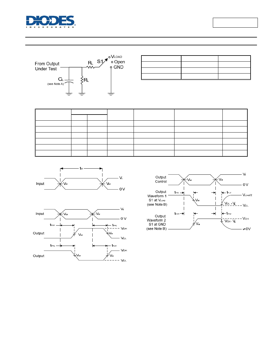
Parameter measurement information – Diodes 74AUP1G125 User Manual
Page 9
74AUP1G125
Document number: DS35157 Rev. 2 - 2
9 of 15
July 2013
© Diodes Incorporated
74AUP1G125
Parameter Measurement Information
TEST S1 R
L
t
PLH
/t
PHL
Open
1M
Ω
t
PLZ
/t
PZL
Vload
5k
Ω
t
PHZ
/t
PZH
GND
5k
Ω
V
CC
Inputs
V
M
V
LOAD
C
L
V
∆
V
I
t
r
/t
f
0.8V
V
CC
≤3ns
V
CC
/2
2 X V
CC
5, 10, 15, 30pF
0.1V
1.2V ± 0.1V
V
CC
≤3ns
V
CC
/2
2 X V
CC
5, 10, 15, 30pF
0.1V
1.5V ± 0.1V
V
CC
≤3ns
V
CC
/2
2 X V
CC
5, 10, 15, 30pF
0.1V
1.8V ± 0.15V
V
CC
≤3ns
V
CC
/2
2 X V
CC
5, 10, 15, 30pF
0.15V
2.5V ± 0.2V
V
CC
≤3ns
V
CC
/2
2 X V
CC
5, 10, 15, 30pF
0.15V
3.3V ± 0.3V
V
CC
≤3ns
V
CC
/2
2 X V
CC
5, 10, 15, 30pF
0.3V
Voltage Waveform Pulse Duration
Voltage Waveform Enable and Disable Times
Low and High Level Enabling
Voltage Waveform Propagation Delay Times
Inverting and Non Inverting Outputs
Figure 1 Load Circuit and Voltage Waveforms
Notes: A. Includes test lead and test apparatus capacitance.
B. All pulses are supplied at pulse repetition rate
≤ 10MHz.
C. Inputs are measured separately one transition per measurement.
D.
t
PLZ
and t
PHZ
are the same as t
dis.
E.
t
PZL
and t
PZH
are the same as t
EN.
F.
t
PLH
and t
PHL
are the same as t
PD.